CP643E.pdf - 第115页
FK-9F98- 05 CP- 643E Training Text for Service Engineers Edition 5.0 Chapter 7. Camera Adjustment [ 10 / 10] Fuji Machine Mfg. Co., Ltd. Okazaki SMT Equipment Quality Assurance Dept. Technical Support Div. Section No.2 7…
FK-9F98-05 CP-643E Training Text for Service Engineers
Edition 5.0 Chapter 7. Camera Adjustment [9/10]
Fuji Machine Mfg. Co., Ltd. Okazaki
SMT Equipment Quality Assurance Dept.
Technical Support Div. Section No.2
7-9
7.7 Mark Camera Adjustments
7.7.1 Focus Adjustment
Note that before adjusting the mark camera the X0Y0 and the Z0 adjustments must already be
completed, and the proper data input into the machine.
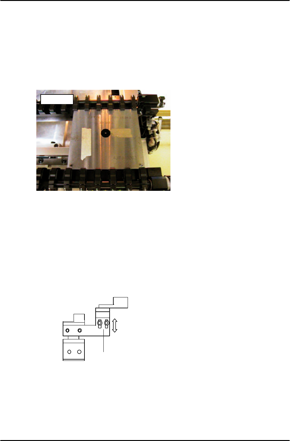
1. Clamp the fiducial jig plate in the main conveyor clamper. Make sure that the two tooling pins fit
smoothly into the two holes in the jig plate. (figure 16)
2. Move the fiducial jig plate under the mark camera by inching. Set the height of the main table to Z0
as follows:
[SET] → [PROPER] → [CAMERA] → [XC/YC] → [Z0] → START
NOTE: Z0 must be calibrated before carrying out this adjustment. When focusing the mark camera,
make sure the table is set at Z0.
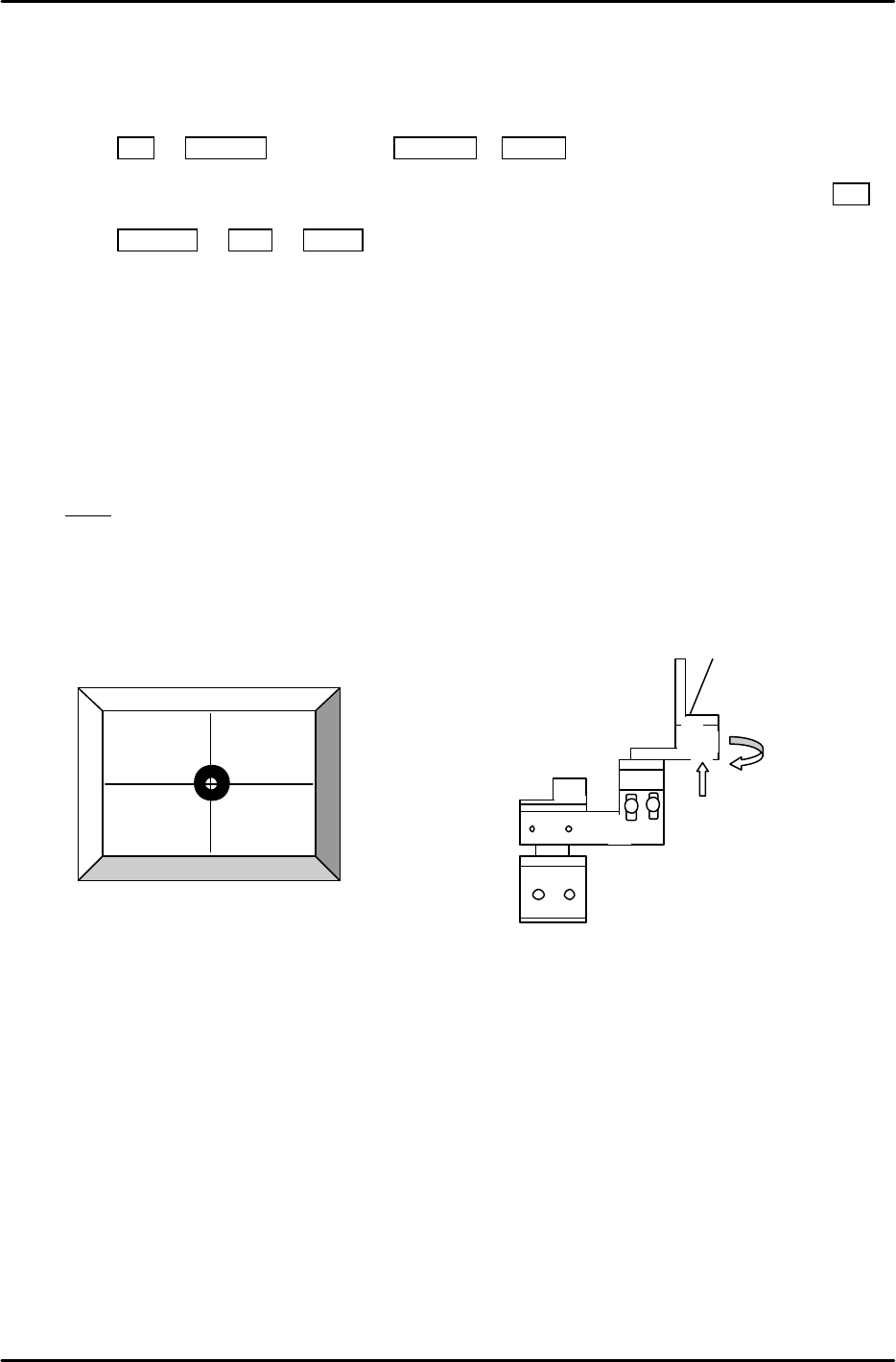
3. Loosen the two height positioning bolts and adjust the focus by raising or lowering the height of the
camera. (see figure 17)
4. The focus is set when the black circle and silver dot in the center of the mark camera jig are in
clear, sharp focus.
AJPJ0062
Figure 16
2 height
adjustment
bolts.
Figure 17
FK-9F98-05 CP-643E Training Text for Service Engineers
Edition 5.0 Chapter 7. Camera Adjustment [10/10]
Fuji Machine Mfg. Co., Ltd. Okazaki
SMT Equipment Quality Assurance Dept.
Technical Support Div. Section No.2
7-10
7.7.2 Mark Camera Resolution, Skew, and XC YC Calibration
1. Set the table height to Z0. Clamp the XcYc jig using pins at Z0.
2. Press SET à PROPER à ID code à CAMERA à XC/YC.
3. Jog to align the mark on the XcYc jig with the crosshairs on the monitor (fig.18) then press SET.
4. Press RETURN à Mark à START. The resolution and delta will be measured for the mark
camera.
5. Rotate the camera bracket (fig.19) in order to set Delta Q to 0. Then repeat from step 2 again.
(Tolerance ----- less than ±0.05 deg.
Mark camera resolution ----- 18.2 to 19.3 um/pixel
Mark Read Pos Xc should be in the following range:
Mark Read Pos Xc – 45100 to – 45300 (L à R flow) , – 400 to – 600 (RàL flow)
Note! If the PCB was reverse flow, R? L, (reference pin position = left), add 10000 pulses to XC.
6. If outside the prescribed range, loosen the focus adjustment bolts and adjust the height of the
camera. Re-measure the resolution and repeat until the values fall within range.
2 adjustment
bolts here.
Figure 19
Figure 18
FK-9F98-05 CP-643E Training Text for Service Engineers
Edition 5.0 Chapter 8. Placement [1/6]
Fuji Machine Mfg. Co., Ltd. Okazaki
SMT Equipment Quality Assurance Dept.
Technical Support Div. Section No.2
8
-
1
Chapter 8 Placing Accuracy Measurement
8.1 PAM Calibration
[Parts] 3216 for PAM
[PCB] PAM Board 1
[Feeder] TD 8x4 for PAM
[Program] PAMC63(M)N or PAMC63(M)N2
PAMC63(M)W or PAMC63(M)W2
[Double sided tape] Scotch brand
[PAM ROM card] V1.01
PAM (Placing Accuracy Measurement) is a function for measuring the part placing accuracy.
When PAM is started, a correction value for the station 11 (part placing station) proper data is
calculated, and the ST11 proper data is re-entered and saved in accordance with this correction value.
This data is also transmitted back to the host computer (FujiCam, F4G, MCS).
The ST11 proper data acts to correct mechanical positional errors (due to working and mounting error
amounts), resulting in a uniform correction. X and Y direction correction values are entered for each
nozzle. As the system consists of 20 heads with 6 nozzles per head, this results in a total of 240
proper data input items.
Corrections in Station 11 Proper data are required to counter the mechanical deviation of each nozzle
at station 11.
Although the nozzle centers are measured at station 6, (parts cameras) it is impossible to measure the
centers at station 11. The placement position of parts will be inaccurate without compensating for
these mechanical deviations because, it is impossible for each nozzle to stop at the exact same point.
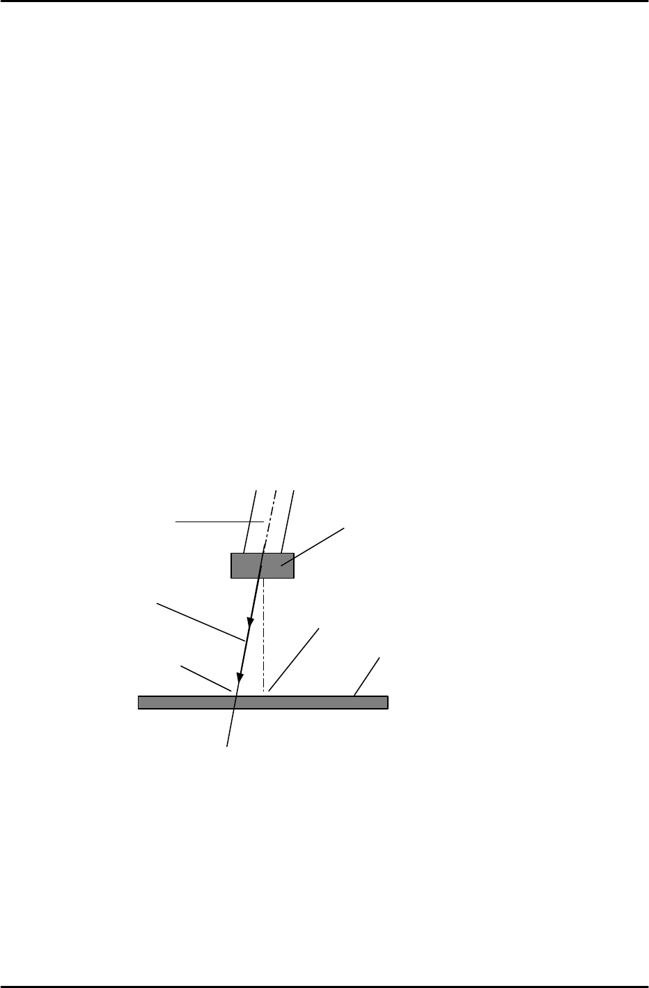
As shown in this illustration, when a nozzle cannot move in a completely vertical direction due to
mechanical errors, the center of a part, as seen by the vision processing system, and the actual center
may not correlate.
The measurement performed by PAM involves a process in which dummy chips are actually placed on
a mark reference board, with the chip placement accuracy being measured by the mark camera. Each
nozzle is rotated to 0, 90, 180 and 270 degrees. The vision processing data for the placed parts then
undergoes statistical processing to provide an accurate measurement of the mechanical error amount.
Note: the following procedure lists the steps needed to perform PAM at the machine. For further details
on PAM and menu displays, please refer to the CP-6 PAM Operation Manual available on the Fuji
web-site.
Part
Nozzle
Board
Parts center
at placement
Descending
trajectory
Part center detected
by Vision processing