CP643E.pdf - 第34页
FK-9F98-05 CP-643E Training Text for Service Engineers Edition 5.0 Chapter 3. X, Y, Z and D-axes Adjustment [ 15 /26] Fuji Machine Mfg. Co., Ltd. Okazaki SMT Equipment Quality Assurance Dept. Technical Support Div. Secti…
FK-9F98-05 CP-643E Training Text for Service Engineers
Edition 5.0 Chapter 3. X, Y, Z and D-axes Adjustment [14/26]
Fuji Machine Mfg. Co., Ltd. Okazaki
SMT Equipment Quality Assurance Dept.
Technical Support Div. Section No.2
3-14
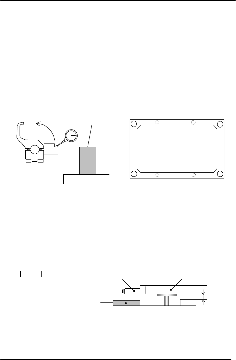
3.10 Back-up Plate Height and Flatness Adjustment
1. After zero-setting the Z-axis, raise the table to 5000 pulses. Place the height
adjustment jig on the backup plate.
2. Adjust the 4 bolts so the top surface of the jig and clamper base are equal.
3. Note: When changing the Z-axis position, the spring force to the plate changes
and the jig’s height will slightly differ. Please pay attention when adjusting.
(Adjust it within range so that the Z-axis and backup plate are synchronized.)
4. Flatness tolerance ----- less than 0.1mm
(There are 4 adjustment bolts. It is better to set one height as reference and measure with a
dial gauge.)
3.11 Back-up Pin Interference Prevention Sensor Adjustment
1. Adjust the 4 flags so the sensors will turn ON, when the clearance between the Y-table and the
backup plate is 2mm. (Set the flags so the 4 sensors activate within 50 pulses of each other.)
2. Check the sensor reaction in I/O.
<I/O ? Standard I/O? IN>
X031 Back up Pin Check
Back up plate
Jig
Z5313WPJ0130
Figure 20
Figure 21
Adjustment bolts
Adjustment bolts
Backup Plate
Flag
Proximity SW
2mm
Figure 22
FK-9F98-05 CP-643E Training Text for Service Engineers
Edition 5.0 Chapter 3. X, Y, Z and D-axes Adjustment [15/26]
Fuji Machine Mfg. Co., Ltd. Okazaki
SMT Equipment Quality Assurance Dept.
Technical Support Div. Section No.2
3-15
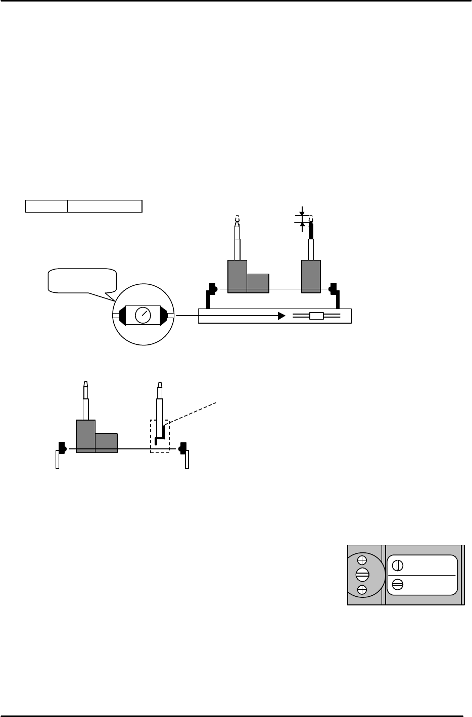
3.12 PCB Set Check Sensor Adjustment
1. Adjust the sensor BKT so that the light axis comes to the center of the reference pin
and secondary pin block hole.
2. Set the sensor so it turns OFF when both the reference and adjustable pins move down
1.0 to 1.5mm.
3. As for the adjustable pin, the sensor should react at maximum, mid and minimum
pitches. Make sure that the green LED is always on.
4. Check the sensor reaction in I/O
< I/O à Standard I/O à IN>
X033 PCB SET OK
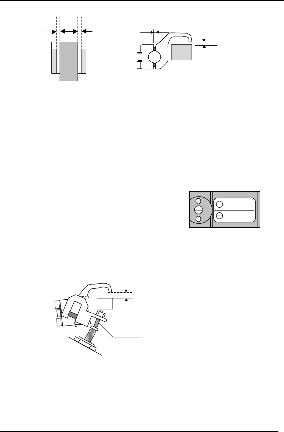
3.13 Main Conveyor PCB Clamping Claw Check and Adjustment
3.13.1 (Part 1) Claw Positioning Adjustment
1. Check that the reference pin switch valve is set to “Mark Ref”.
2. Lock the rail-clamping claw at the closed position by solenoid valve.
3. Check that all the individual claws are loose.
4. There is some play in the position of the rail-clamping claw center bracket, so check that this is set
at the center of the play.
5. The next step is to lock all the individual claws. When these are locked, the clearance between the
tip of the claw and the guide rail should be in the range of 0.03 – 0.10 mm. (A) Each claw should be
locked using a 4Nm torque wrench. However, before proceeding to lock each claw, there are some
other considerations to bear in mind. Refer to figure 25.
Mark Ref.
Pin Ref.
Figure 24
1.0 to 1.5mm
M
AX
MIN
Set to MAX.
Figure 23
When the pin is pressed
down this flag cuts the
sensor beam. When
replacing the pin ensure that
the flag is long-side up.
FK-9F98-05 CP-643E Training Text for Service Engineers
Edition 5.0 Chapter 3. X, Y, Z and D-axes Adjustment [16/26]
Fuji Machine Mfg. Co., Ltd. Okazaki
SMT Equipment Quality Assurance Dept.
Technical Support Div. Section No.2
3-16
6. Proceed to lock each claw making sure that the clearance values are within the ranges shown
above. It may be useful to lock the two center claws and the two claws at both ends of the rail first,
then proceed to lock the claws in between. Remember that clearance between the tip of the claw
and the guide rail should be in the range 0.03 to 0.10 mm. The claw is attached to the rail by two
3mm bolts. Tightening the top bolt will increase the clearance, tightening the bottom bolt will
decrease the clearance.
3.13.2 (Part 2) Claw Float Adjustment
1. Set the reference pin switch valve to “Pin Ref”.
2. Place a 4mm thick PCB in the main conveyor clamper.
3. Activate but do not lock the adjustable rail clamping solenoid.
4. At this position, there should be 0.5mm clearance between the clamper claw tips and the PCB.
5. Use the adjusting bolt on the claw float cylinder to set the clearance at 0.5mm. Note that the
clearance will vary slightly at different points on the clamper rail. Set the 0.5mm clearance at the
narrowest point.
6. On the fixed rail side, set the position of the clamping claw float sensor flag so that the sensor LED
is OFF when a 4mm thick PCB is clamped and ON when a 4.5mm PCB is clamped. Note that the
clamping solenoid should be activated but not locked for this adjustment. I.e. In this case “clamped”
means press the clamping solenoid once but do not lock it. Note: the sensor is Dark-On so when the
LED is Off the I/O input is ON, and vice versa. I/O: (X032 PCB Set CLP OK).
* Note that 0.5mm clearance on both sides is the ideal. However, this may be difficult to
achieve. In such cases a rough balance between the two is acceptable.
0.5mm0.5mm *
0.03 to 0.10 mm
(A)
0.9 mm
Figure 25
Mark Ref.
Pin Ref.
Figure 26
4.5mm
Adjustment Bolt
Figure 27