CP643E.pdf - 第25页
FK-9F98-05 CP-643E Training Text for Service Engineers Edition 5.0 Chapter 3. X, Y, Z and D-axes Adjustment [ 6 /26] Fuji Machine Mfg. Co., Ltd. Okazaki SMT Equipment Quality Assurance Dept. Technical Support Div. Sectio…
FK-9F98-05 CP-643E Training Text for Service Engineers
Edition 5.0 Chapter 3. X, Y, Z and D-axes Adjustment [5/26]
Fuji Machine Mfg. Co., Ltd. Okazaki
SMT Equipment Quality Assurance Dept.
Technical Support Div. Section No.2
3-5
3.4 X and Y Axes Backlash Check
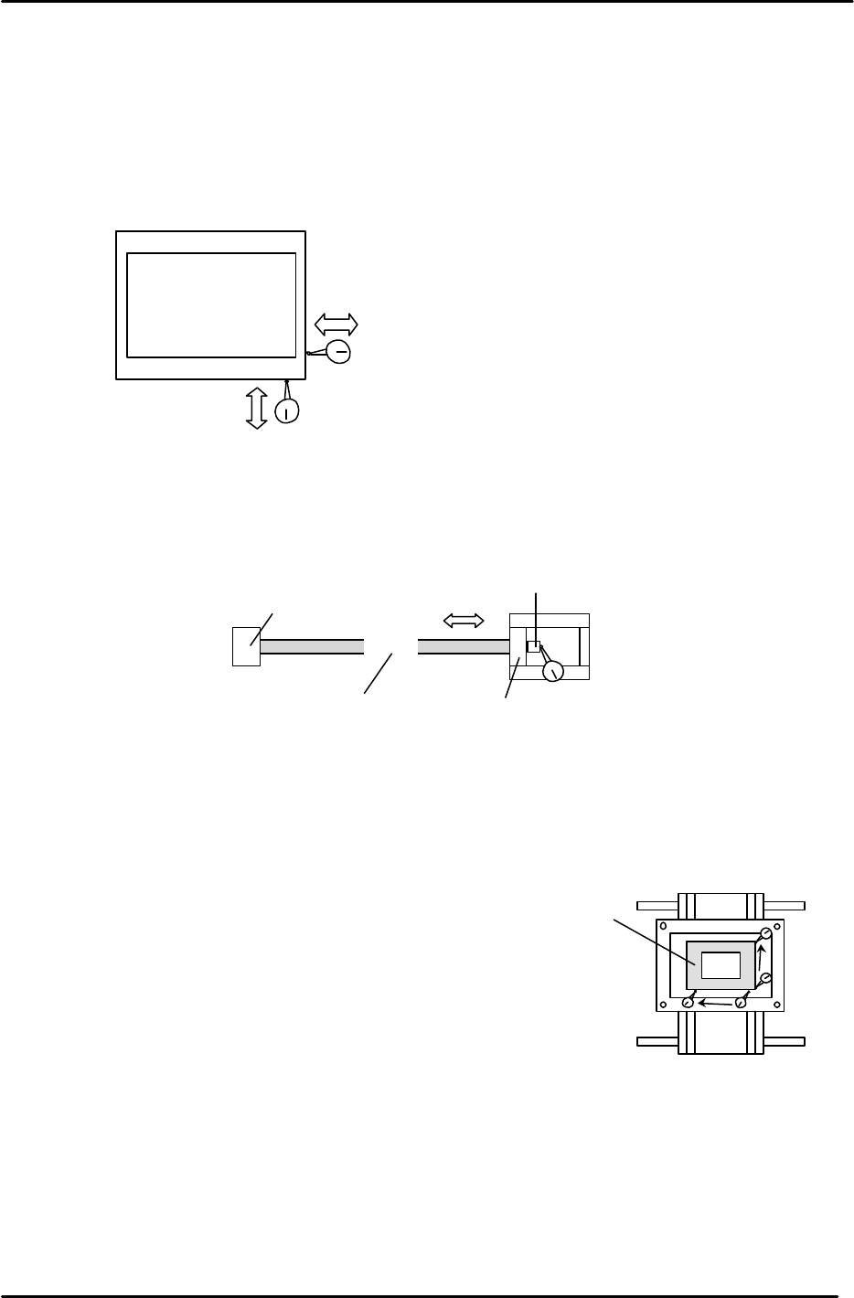
1. Place a (0.002mm) dial gauge against the X-axis of the XY table (Fig.4). Make sure the servo
power is ON, push the XY table left and right by hand to check the amount of backlash.
(Tolerance: 0.010mm.)
2. Check the Y axis in the same manner. Make sure the servo power is ON, push the XY table
backwards and forward to check the amount of backlash. (Tolerance: 0.010mm.)
3. If the amount of backlash is out of tolerance, check the following 2 areas.
a. Ball nut
b. Ball screw bearings
3.5 X/Y Table Squaring Check
Check the squaring of the X/Y table using the jig plate.
(Jig No.: Z9913AWPJ9560)
1. Align the jig in the Y direction to zero using a dial gauge.
2. Indicate the jig face in the X direction to check table squaring.
(Tolerance: 0.015 / 239mm)
XY Table
Backlash check in the X direction
Backlash check in the Y direction
Figure 4
Ball Nut
Bearing
Bearing
Indicate here to check bearings
Coupling box
Figure 5
Squaring Jig
Figure 6
FK-9F98-05 CP-643E Training Text for Service Engineers
Edition 5.0 Chapter 3. X, Y, Z and D-axes Adjustment [6/26]
Fuji Machine Mfg. Co., Ltd. Okazaki
SMT Equipment Quality Assurance Dept.
Technical Support Div. Section No.2
3-6
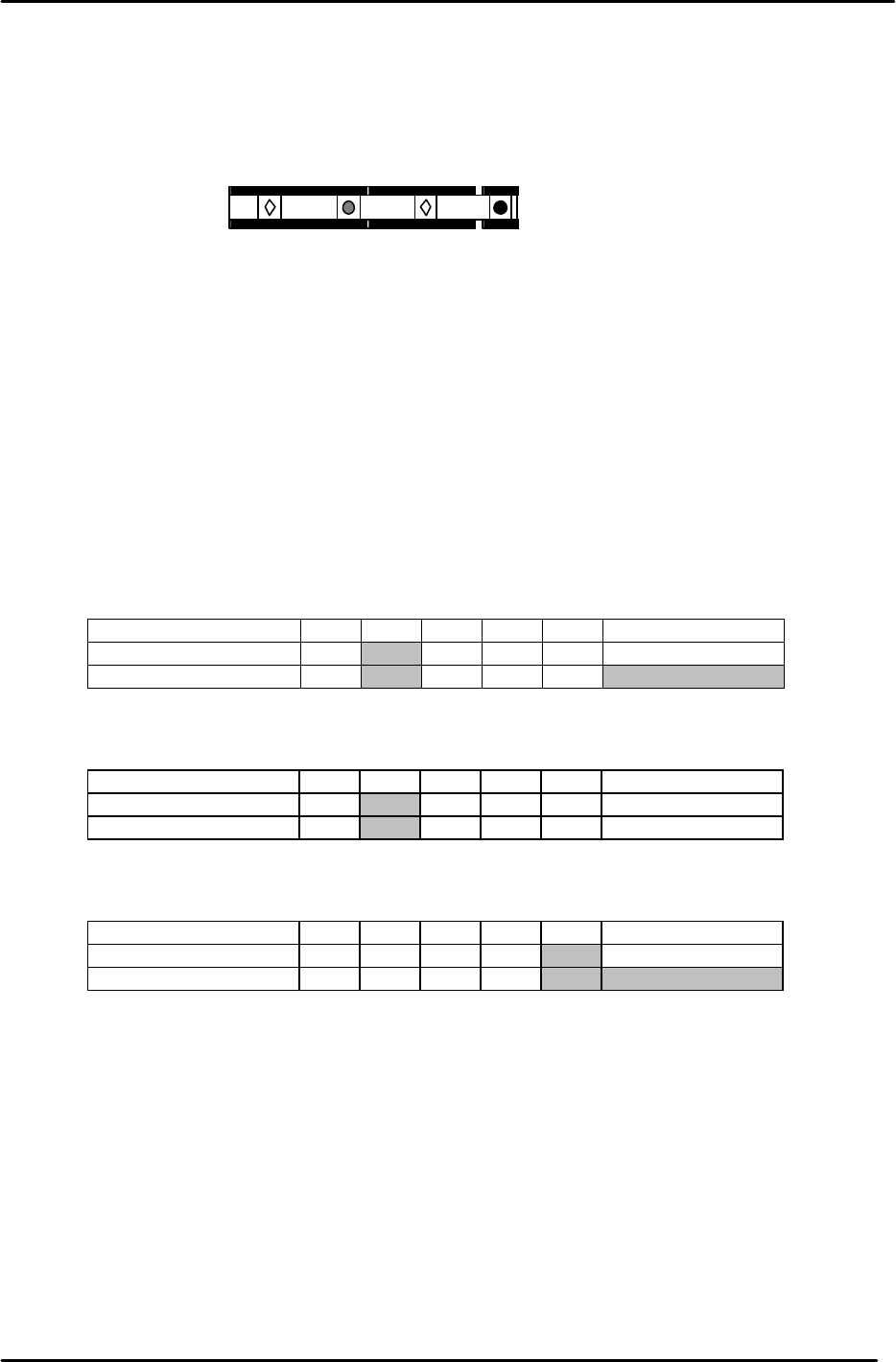
3.6 Reference and Adjustable Pin Alignment Check
Check the alignment and play of the tooling pins as follows.
1. The diagram below shows the tooling pin configuration for the CP-643E.
2. To check the alignment of the four pins, place a dial gauge (0.002mm) against reference pin A
and set it to 0.
3. Inch the X/Y table in the X direction and measure the alignment of the three other pins in
relation to reference pin A .
4. Measure at the points indicated in the tables below:
Measuring Point (mm) Max 370 270 170 70 Reference pin A
Center Position 0
Backlash Value
Measuring Point (mm) Max 370 270 170 70 Reference pin A
Center Position 0
Backlash Value
Measuring Point (mm) Max 370 270 170 70 Reference pin A
Center Position 0
Backlash Value
Secondary Pin A:
Reference Pin B:
Center Position Tolerance: +/- 0.020mm. Backlash Tolerance: 0.040mm.
Secondary Pin B:
Center Position Tolerance: +/- 0.050mm. Backlash Tolerance: 0.040mm.
Center Position Tolerance: +/- 0.050mm. Backlash Tolerance: 0.040mm.
Reference pin A
Reference pin B
Secondary pin A
Secondary pin B
Figure 7
FK-9F98-05 CP-643E Training Text for Service Engineers
Edition 5.0 Chapter 3. X, Y, Z and D-axes Adjustment [7/26]
Fuji Machine Mfg. Co., Ltd. Okazaki
SMT Equipment Quality Assurance Dept.
Technical Support Div. Section No.2
3-7
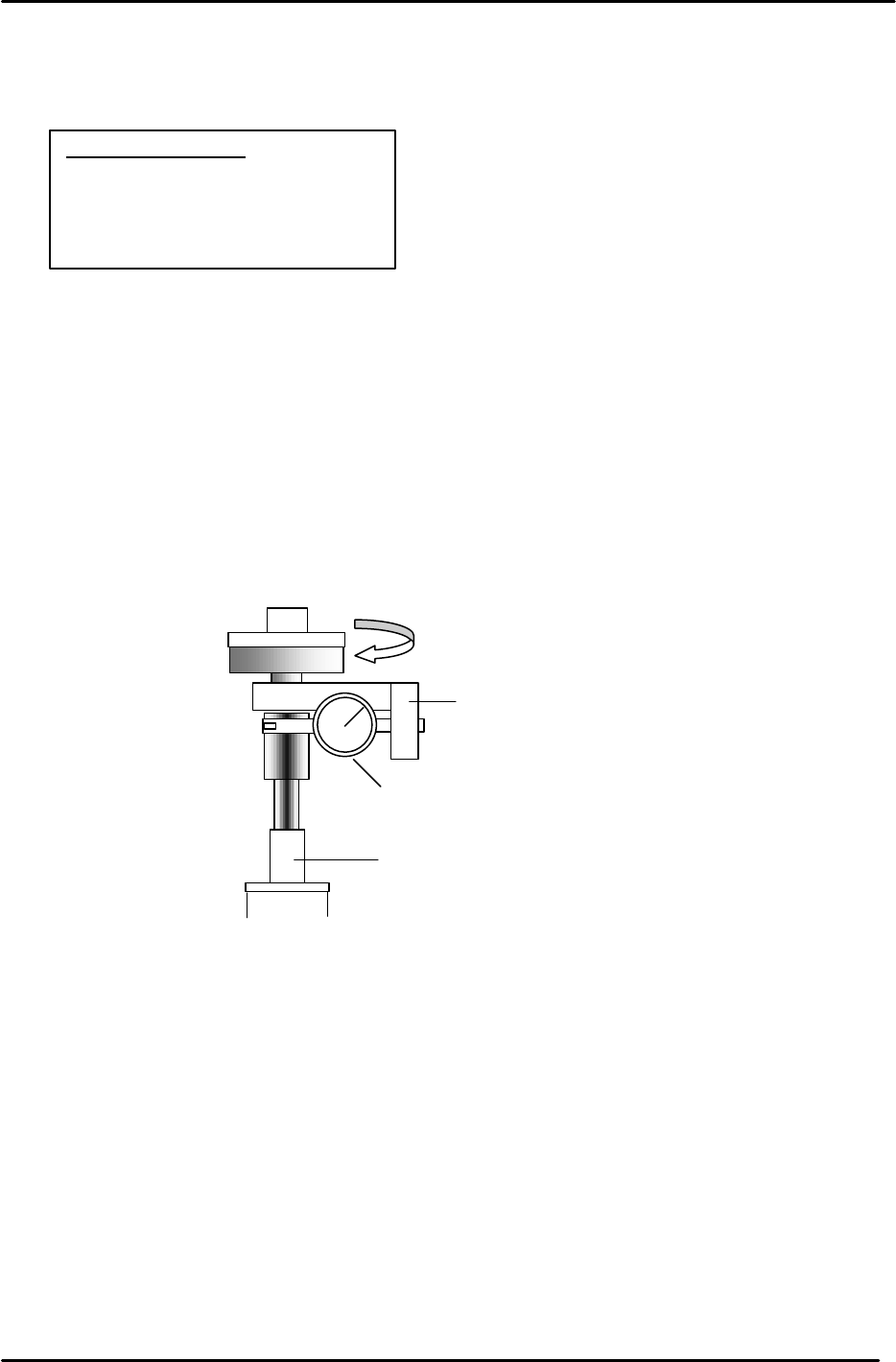
3.7 X0/Y0 Proper Measurement
X0/Y0 is the placing origin position. Follow the procedure below to carry out the adjustment.
1. Zero set the X and Y axes.
2. Remove the nozzle holders from shafts A, B, and T.
3. Remove the main reference pin and spring then replace the pin holder.
4. Remove the first claw on the reference rail right side.
5. With the cam at 0 degrees, use the I/O to turn the 11th station place solenoid OFF.
6. Attach the X0/Y0 dial gauge set-up on shaft A. (Jig No.: AWPJ9030)
7. Insert the reference pin jig.
8. Measure with the cam angle at 200 degrees.
9. Press the emergency stop button so the machine goes to a servo down condition.
10. Make sure the Z- axis is at the lower limit.
11. Move the XY table manually until the reference pin jig meets the dial gauge on the A holder.
12. Move the table very carefully by hand (using the couplings) until you find the point where the
dial gauge is zero throughout the circumference of the reference pin jig. (Tolerance 0+/-
0.01mm)
13. When the position is established, enter the servo counter value into the proper at the host PC.
14. Finally, remember to remove the dial gauge and jig, but leave the reference pin out until after
the next adjustment: 3-8 XY Table Level Check.
Equipment Checklist:
1- X0/Y0 origin pin jig
1- X0/Y0 special dial gauge set up
1- 3mm L-wrench
1- Small mirror
Figure 8
Main reference
pin holder
Dial gauge holder
Dial indicator
Jig
AWPJ9030