CP643E.pdf - 第29页
FK-9F98-05 CP-643E Training Text for Service Engineers Edition 5.0 Chapter 3. X, Y, Z and D-axes Adjustment [ 10 /26] Fuji Machine Mfg. Co., Ltd. Okazaki SMT Equipment Quality Assurance Dept. Technical Support Div. Secti…
FK-9F98-05 CP-643E Training Text for Service Engineers
Edition 5.0 Chapter 3. X, Y, Z and D-axes Adjustment [9/26]
Fuji Machine Mfg. Co., Ltd. Okazaki
SMT Equipment Quality Assurance Dept.
Technical Support Div. Section No.2
3-9
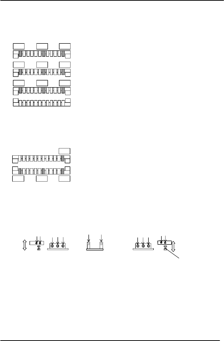
6. (Final leveling check) The reference point for measuring the table flatness is the far right claw on
the adjustable rail, when it is 50mm from the fixed rail (indicated by a 0 in Fig.11). Measure the rail
flatness at the nine points identified in Fig.11.
(Tolerance: +/- 0.15mm,)(factory target +/- 0.1mm)
7. If the adjustable rail is not flat at the locations illustrated, it may be necessary to repeat step 5.
8. Once the adjustable rail flatness is within tolerance. Use the 0 position (Fig.12) as the reference to
check the height between the adjustable and reference rails at the hi-lighted positions.
9. If the height of the reference rail is more than +/-0.1mm than that of the adjustable rail, (or the
reference rail itself is uneven) adjust the reference rail height (flatness), by loosening the bolts
indicated in Fig. 13 and adjust, using the bolts under both sides of the reference rail.
Adjustable rail at
250
mm
Adjustable rail at 50mm
Adjustable rail at 150mm
Reference Rail
0
Figure 11
Reference Rail
Adjustable rail at 50mm
0
Figure 12
Adjustment bolt
12 Securing bolts
Figure 13
4mm
Bolts
4mm
Bolts
3mm
Bolts
4mm
Bolts
FK-9F98-05 CP-643E Training Text for Service Engineers
Edition 5.0 Chapter 3. X, Y, Z and D-axes Adjustment [10/26]
Fuji Machine Mfg. Co., Ltd. Okazaki
SMT Equipment Quality Assurance Dept.
Technical Support Div. Section No.2
3-10
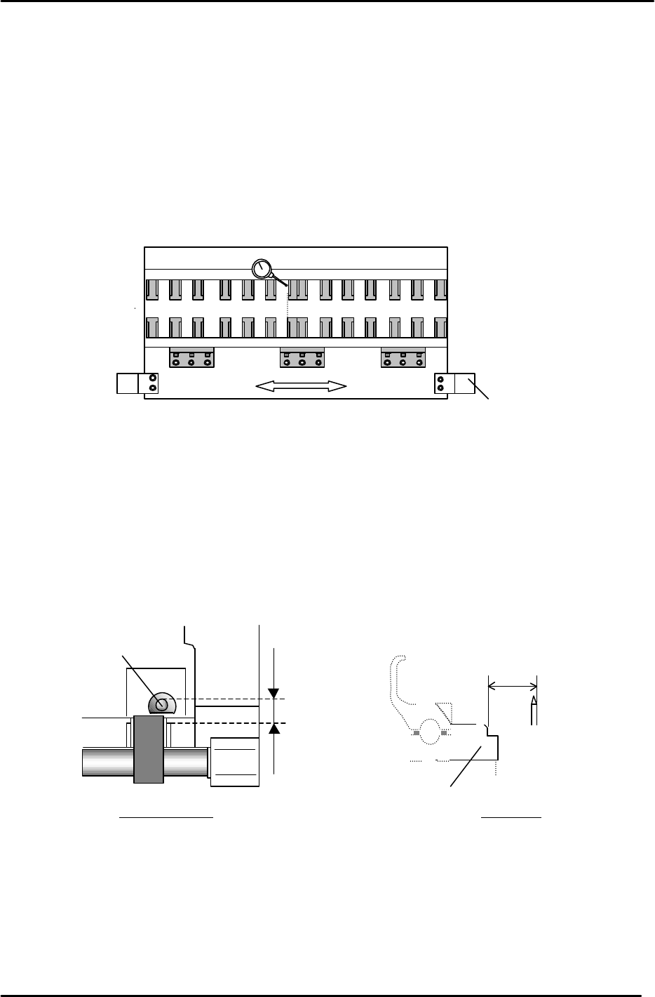
3.8.2 (Part 2) Reference and Adjustable Rail Alignment in the Y direction
1. The two rails should be aligned to within 0.1mm. (with the adjustable rail at the center of
play)
2. Disconnect the air pressure to the machine and move the adjustable rail left and right to
establish the center of play using a dial gauge.
3. Reattach the air.
4. Align the reference rail to the adjustable rail (center of play) by loosening the bolts indicated
in Fig.14.
3.8.3 (Part 3) Origin Pin To Claw Position Adjustment
1. The distance from the origin pin to the claw should be between 700 and 720 pulses.
2. Install the origin pin and spring.
3. Using a dial gauge, set the distance from the pin to the claw, by moving the reference rail in
the Y direction. (set the distance as close to 705 pulses as possible)
Adjustable rail
Reference rail
Clamping cylinder
* Loosen 13 bolts
*
*
*
*
*
*
*
*
*
*
*
*
*
Figure 14
700 to 720
Pulses
Origin Pin
Overhead View
3mm Origin Pin
700 to 720 Pulses
(7mm to 7.2mm)
Claw
Side View
Figure 15
FK-9F98-05 CP-643E Training Text for Service Engineers
Edition 5.0 Chapter 3. X, Y, Z and D-axes Adjustment [11/26]
Fuji Machine Mfg. Co., Ltd. Okazaki
SMT Equipment Quality Assurance Dept.
Technical Support Div. Section No.2
3-11
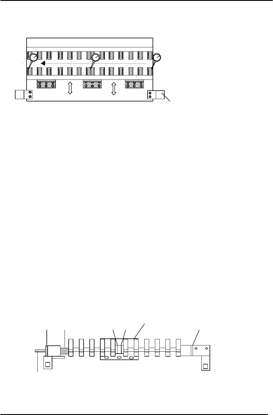
4. After the positioning has been completed in part 3, an alignment check of the reference rail in
the X-direction is necessary. Carry out the alignment check as indicated in Fig 16.
(Tolerance: within 0.1mm.)
5. Check the following positions again, after completing step 4, to ensure they remain within
tolerance.
3-8.1 (Part 2) – Reference and Adjustable Rail Alignment in the Y direction
3-8.1 (Part 3) – Origin Pin To Claw
3.8.4 (Part 4) Mechanical Lock Ring Adjustment
1. On the reference rail, check that the gap between the white plastic washer and the far right clamper
bracket is less than 0.3mm. If not, loosen the mechanical lock and the bolts on the far right clamper
bracket, then adjust the position of the clamper rod until the gap closes.
2. Check that the center base of the reference rail is pulled right up against the lip of the reference rail.
Check that a 0.03mm feeler gauge cannot go into the gap between the two.
3. Confirm all of the claws on the reference rail are loose and then loosen the mechanical lock.
4. Lock the reference rail at its unclamp position.
5. With the reference rail unclamped, lock the four bolts (on the mechanical lock) in rotation with a 2Nm
torque wrench.
6. For details of the location of various parts described above see Fig.17.
7. Finally clamp and unclamp the reference rail to check the clamping balance between the left and
right clamping brackets. If there is an imbalance, repeat steps 3 to 5 above until a balance is
achieved.
Reference rail
Clamping cylinder
* Loosen 13 bolts
*
*
*
*
*
*
*
*
*
*
*
*
*
Figure 16
Clamper Rod
Washer 1
Washers 2 and 3
Spring
Fixed Rail Clamper Assy. Positioning
Center Base
Mechanical lock
Figure 17