CP643E.pdf - 第93页
FK-9F98-05 CP-643E Training Text for Service Engineers Edition 5.0 Chapter 6. Servo Pack Zero Setting and Gain/ Motion Check [ 2 / 14] Fuji Machine Mfg. Co., Ltd. Okazaki SMT Equipment Quality As surance Dept. Technical …

FK-9F98-05 CP-643E Training Text for Service Engineers
Edition 5.0 Chapter 6. Servo Pack Zero Setting and Gain/ Motion Check [1/14]
Fuji Machine Mfg. Co., Ltd. Okazaki
SMT Equipment Quality Assurance Dept.
Technical Support Div. Section No.2
6
-
1
Chapter 6 Servo Pack Zero Setting and Gain/Motion Check
6.1 Servo Amplifier Parameter Check
1. Check the parameters for each axis according to the servo amplifier parameter chart shipped with
every machine.
6.2 Servo Pack Zero Adjustment Preparation
1. After idling for 10 hours, carry out servo adjustment and zero adjustment.
2. If any problems occur during idling, carry out zero adjustment, and after idling (10 hours), carry out
zero adjustment again.
3. Zero set before booting up the mechanical check software.
4. Mechanical check software, servo adjustment software, is used to adjust the servo system on the
CP643E. The following is the servo adjustment instruction using the software. This instruction is
supported by servo ROM 305 or after.
5. Boot the mechanical check software.
3 ( Axis change-SW)+ RESET + POWER ON
6. Set each cam lever stopper as follows by I/O. (Operate only at 0 degrees)
Y014 SHUTTER1 UP ? Y028 PLACE SOL ON ×
Y015 SHUTTER1 DOWN × Y029 PLACE SOL OFF ?
Y016 SHUTTER2 UP ? Y02A NOZ SOL ON ×
Y017 SHUTTER2 DOWN × Y02B NOZ SOL OFF ?
Y020 PICKUP SOL ON × Y02C PRQ ROT.SOL ON ×
Y021 PICKUP SOL OFF ? Y02D PRQ ROT.SOL OFF ?
Y022 PQ ROT SOL ON × Y02E PRQ ROT 90DEG ×
Y023 PQ ROT SOL OFF ? Y02F PRQ ROT 270DEG ?
Y024 PQ ROT 90DEG ? Y030 FQ SOL ON ×
Y025 PQ ROT 270DEG × Y031 FQ SOL OFF ?
Y026 TAPE FEED SOL ON ×
Y027 TAPE FEED SOL OFF ?
7. Select the axis to be adjusted.
SERVO (F5) ? +PAGE , -PAGE
8. Select the servo activating mode.
SERVO MOVE (F1)
9. Zero set.
MOVE MODE (F4)? Select “zero set mode”.
(“zero set mode” and “test move mode” switches alternately.) SERVO ON (F1)? START
10. Zero set the axis to be adjusted.
FK-9F98-05 CP-643E Training Text for Service Engineers
Edition 5.0 Chapter 6. Servo Pack Zero Setting and Gain/ Motion Check [2/14]
Fuji Machine Mfg. Co., Ltd. Okazaki
SMT Equipment Quality Assurance Dept.
Technical Support Div. Section No.2
6
-
2
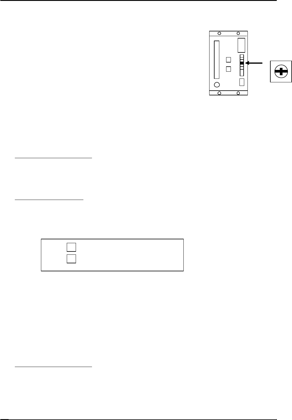
6.3 D-axis Servo Pack Zero Adjustment
1. In mechachek mode, press [V_TEST] (F3) → [ZERO] (F3) → [START]
2. Adjust the “ZERO” volume pot on the servo amplifier to
stabilize the counter value.
3. Press the E–stop after the counter value becomes stable.
6.4 C and X Axis Servo Pack Zero Adjustment
1. Connect a digital operator to the servo amplifier.
2. In mechachek mode, press [V_TEST] (F3) → [ZERO] (F3) → [START]
3. The servo counter value appears on the screen and the value changes.
4. Zero adjust automatically and then manually.
Automatic Zero Adjustment
On the digital operator, press [DSPL SET] → [CN – 00] → [DATA ENTER] → [00-00]
→ [press the up arrow to display 00-01] → [DSPL SET] The flashing display will pause for
a second then begin flashing again.
Manual Zero Adjustment
On the digital operator, [press the up arrow to display 00-03] →[DSPL SET] → Press once
to [A_ ###] → [Press the up/down arrow keys on the digital operator in order to stabilize
the counter value.
? … Offset toward positive.
? … Offset toward negative.
When the value stabilizes, press → [DSPL SET] and the data will be memorized.
Press [CYCLE STOP] to stop the adjustment ? [DATA ENTER] ? [CN-00]
6.5 FQ, FRQ, NC, Y, and Z axis Servo Pack Zero Adjustment
1. Adjust using the keys on the face of the servo pack.
2. Perform Automatic and then Manual zero adjustments.
Automatic Zero Adjustment
1. Press an emergency button.
2. Press [MODE / SET] ? [FN 000] ? [Up arrow] ? [FN 009] ? [DATA/SHIFT] (for more
than one second) ? [REF – 0] ? [MODE SET] ? [done] (blinks for one second) ? then
press, [REF – 0] ? [DATA SHIFT] (for more than 1 second) ? [FN 009].
ZERO
FK-9F98-05 CP-643E Training Text for Service Engineers
Edition 5.0 Chapter 6. Servo Pack Zero Setting and Gain/ Motion Check [3/14]
Fuji Machine Mfg. Co., Ltd. Okazaki
SMT Equipment Quality Assurance Dept.
Technical Support Div. Section No.2
6
-
3
Manual Zero Adjustment
1. Release the E-Stop to apply servo power.
2. Press [V_TEST] (F3) → [ZERO] (F3) → [START]
3. The servo counter value will display on the monitor and the value changes.
4. Press [MODE / SET] ? [FN 000] ? [Up arrow] ? [FN 00A] ? [DATA/SHIFT] (for more than one
second) ? [S. PD] ? [DATA/SHIFT] ? [####]? [Press the up/down arrow keys on the face of the
servo pack in order to stabilize the counter value.
? … Offset toward positive.
? … Offset toward negative.
5. After the counter value becomes stable, press [DATA/SHIFT] ? [S. PD] ? [DATA/SHIFT]
(for more than 1 second and the data will be memorized.)
6. Press the Emergency Stop ? [DATA/SHIFT] ? [FN 00A]
7. Procedure complete
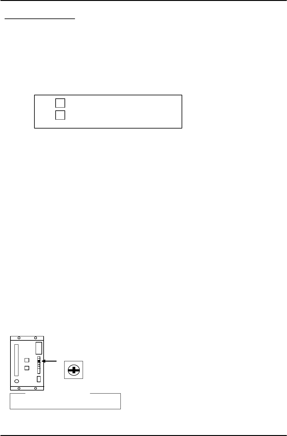
6.6 D-axis Gain / Motion Check
1. When adjusting the gain and motion of the D-axis, do so with NO feeders attached to the tables.
2. Select the D-axis ? [SERVO MOVE] ? [SERVO ON] ? [START] to zero set.
3. Press ? [MOVE MODE] ? “Test move mode” ? [MODE] ? [GAIN TEST ] ? [START]
The following items will be displayed on the monitor:
* Movement time in milliseconds.
* Maximum over shoot amount in pulses.
4. Check that the movement time and overshoot are within the ranges specified in chart 1. (page 6-5)
5. Slowly turn the “LOOP” pot on the D- axis servo amplifier so that both values are within tolerance.
L O O P
? Reference?
D-axis : 7.5 scale