CP643E.pdf - 第77页
FK-9F98-05 CP- 643E Training Text for Service Engineers Edition 5.0 Chapter 5. Loader and Conveyor Adjustment [ 14 / 28 ] Fuji Machine Mfg. Co., Ltd. Okazaki SMT Equipment Quality Assurance Dept. Technical Support Div. S…

FK-9F98-05 CP-643E Training Text for Service Engineers
Edition 5.0 Chapter 5. Loader and Conveyor Adjustment [13/28]
Fuji Machine Mfg. Co., Ltd. Okazaki
SMT Equipment Quality Assurance Dept.
Technical Support Div. Section No.2
5-
13
10. Divide the total pulse count found in step 8, by half. The result should be around the
center of the silver sticker and close to the YL pulse count. (Check the YL proper data) If
not, adjust the sensor head position accordingly. (Balance is the key point)
11. Set the Z- axis to the minus stopper position and set the sensor to the B mode, by pressing
the mode and up keys quickly. Using the “B” mode, set the sensor sensitivity to 100P.
12. Return to the “A” mode and check the sensor performance while raising and lowering the main
table. If problems exist, repeat the procedure outlined above.
13. Lock the sensor settings by pressing both the up and mode keys simultaneously for more than
3 seconds.
<I/O → Standard → IN>
X0C0 Adjusting Rail Engagement Check IN
X0DB Adjusting Rail Engagement Check OUT
X0DC Adjusting Rail Engagement Check Center
Hints For Adjusting the Moveable Rail Engagement Check Sensors
1. First clean the sensor target stickers, as any dirt, grease or dust will effect the sensor readings.
2. Always engage with the carrier first then descend and calculate the center position. Failure to do this
will result in erroneous results.
3. If the beam is in the center of the silver target when engaged with the rail, but is off center when the
table descends to Z0, then the sensor bracket is tilted. In this case calculate where the center is at
Z0. Is it more positive or more negative in relation to YL?
If the center at Z0 is more negative in relation to YL then the sensor is tilted towards the front of the
machine. In this case tilt it in the opposite direction a little using the play in the bracket.
Having done this ascend the XY tablet to engage with the carrier and use the forward/backward
adjusting bolt to reposition the sensor beam in the center of the sticker.
If the center at Z0 is more positive in relation to YL then the sensor is tilted towards the back of the
machine. In this case tilt it in the opposite direction a little, using the play in the bracket.
Having done this ascend the XY tablet to engage with the carrier and use the forward/backward
adjusting bolt to reposition the sensor beam in the center of the sticker.
FK-9F98-05 CP-643E Training Text for Service Engineers
Edition 5.0 Chapter 5. Loader and Conveyor Adjustment [14/28]
Fuji Machine Mfg. Co., Ltd. Okazaki
SMT Equipment Quality Assurance Dept.
Technical Support Div. Section No.2
5-
14
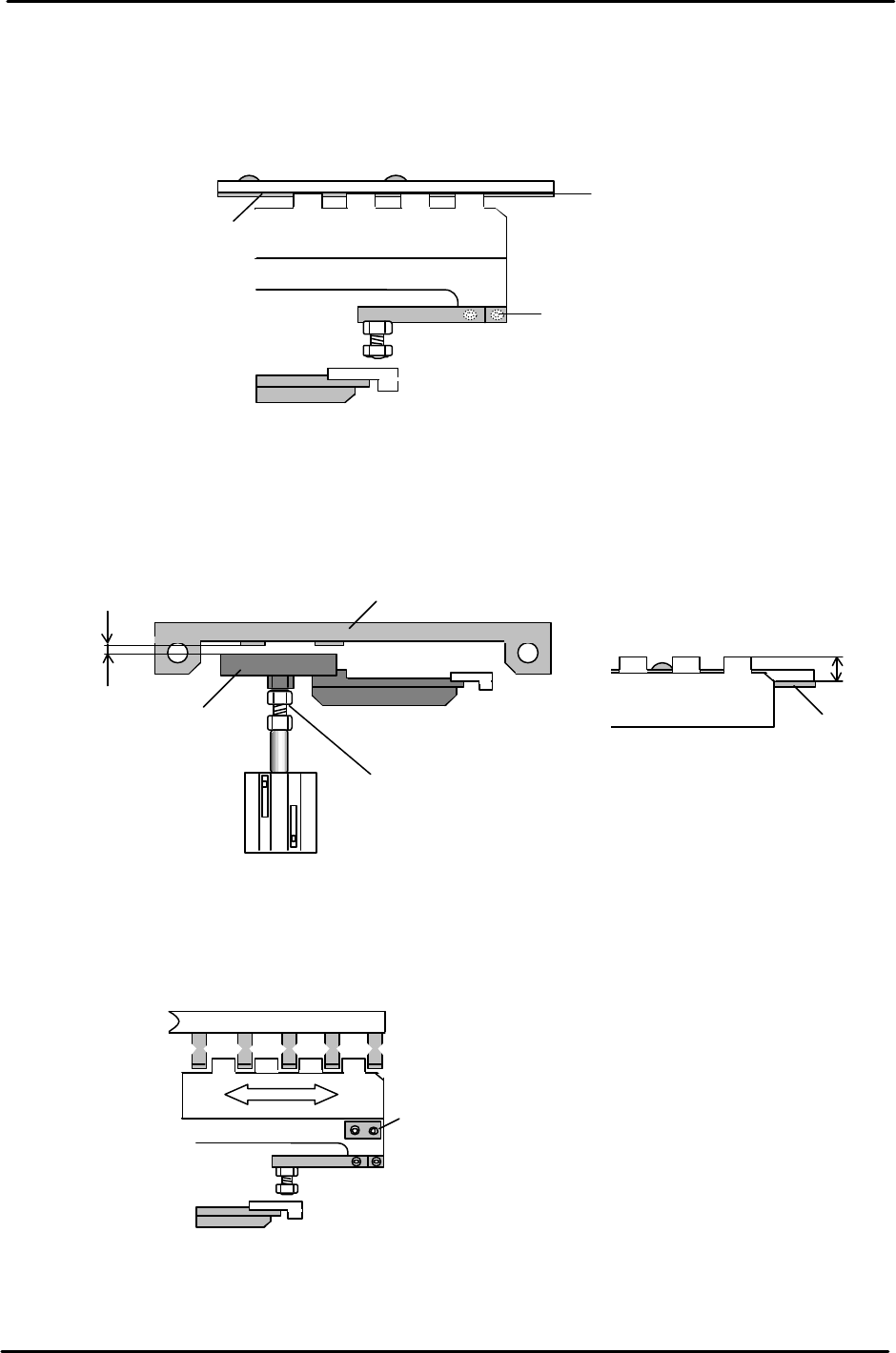
5.16 IN and OUT Conveyor PCB Lifter
1. Lower the PCB lifter for the IN/OUT conveyor and adjust the lifter plate (after
loosening the mounting screws) to align with the center of the conveyor belt.
2. Adjust the clearance between the PCB detection sensor bracket and the plate shown below
between 0.5 to 1.0mm, by adjusting the cylinder rod end.
3. Move the IN and OUT carriers to the backward end position. Loosen the lifter plate mounting
screws and adjust so the clearance between the carrier claws and lifter plate is uniform.
Mounting
Screws located
at both ends of the lifter plate.
(accessible with the lifter down)
Figure 24
Conveyor belt
Lifter Plate
Mounting Screws
C
L
Figure 22
Conveyor Belt
11mm
Plate
Sensor bracket
0.5 to 1.0mm
Cylinder rod end
Figure 23
FK-9F98-05 CP-643E Training Text for Service Engineers
Edition 5.0 Chapter 5. Loader and Conveyor Adjustment [15/28]
Fuji Machine Mfg. Co., Ltd. Okazaki
SMT Equipment Quality Assurance Dept.
Technical Support Div. Section No.2
5-
15
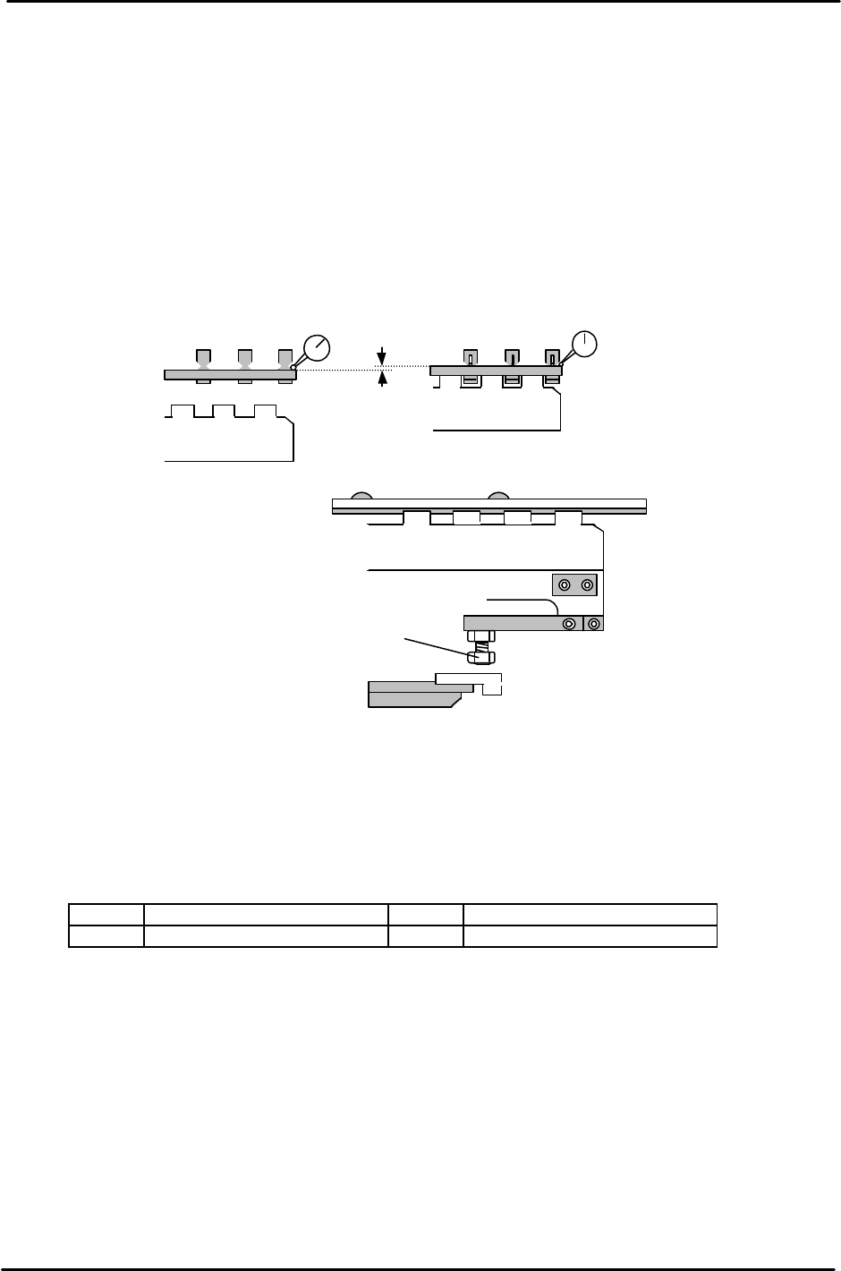
4. To set the lifter height, place a board on the In conveyor, open the carrier claws, raise the lifter,
close the carrier claws and lower the lifter. (The Pcb is now held by the carrier)
5. Raise the lifter when the carrier claw clamps the board.
6. Set a dial gauge on the board as illustrated (two gauges are recommended) Since the dial gauge
cannot normally read 1.2mm, use a 1mm feeler gauge when setting up the dial gauge before
raising the lifter. (Set 1 end first, then the other)
7. When the lifter is raised, the dial gauge should read 0.2 +/-0.1mm. If out of tolerance, adjust the
four bolts as indicated.
8. After adjustment, the lifter should raise the PCB off the carrier claws by 1.2mm.
.
9. For the lifter cylinder sensors, turn both the up and down end sensors ON first. Set the sensors
at a position 0.5mm further in towards the ON position.
10. Check sensor reaction in I/O
<I/O → Standard → IN>
LX01E In-Lifter Upper limit Check LX03E Out-Lifter Upper Limit Check
LX01F In-Lifter Lower Limit Check LX03F Out-Lifter Lower Limit Check
Upper end adjustment bolt (x 4)
Figure 26
1.20mm
<Lifter
Down
>
<Lifter Up>
0 (using 1mm feeler gauge)
0.2 +/- 0.1 (when lifter is raised)
Figure 25