CP643E.pdf - 第66页
FK-9F98-05 CP- 643E Training Text for Service Engineers Edition 5.0 Chapter 5. Loader and Conveyor Adjustment [ 3 / 28 ] Fuji Machine Mfg. Co., Ltd. Okazaki SMT Equipment Quality Assurance Dept. Technical Support Div. Se…
FK-9F98-05 CP-643E Training Text for Service Engineers
Edition 5.0 Chapter 5. Loader and Conveyor Adjustment [2/28]
Fuji Machine Mfg. Co., Ltd. Okazaki
SMT Equipment Quality Assurance Dept.
Technical Support Div. Section No.2
5-
2
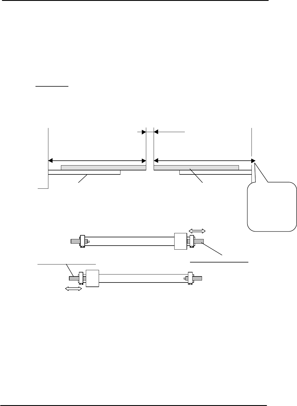
5.3 Carrier Unit Stroke Check
1. Lock the OUT carrier at the forward end and check the stroke as indicated in Fig. 4
2. Adjust the out conveyor forward end shock absorber on the rod-less cylinder so the carrier
position is 556mm from the cut out in the right cam box pillar.
3. Lock both carriers at their forward ends and set a gap of 21.5mm between the two carriers,
by moving the in carrier shock absorber.
4. IMPORTANT: ensure there is a 21.5mm gap between the two carriers. Otherwise,
interference with the main table will result in damage to the machine.
556
mm+/- 0.5mm
21.5mm+/- 0.5mm
In-Carrier Out-Carrier
Cam Box
Pillar
Cam Box
Pillar
Figure 4
IN Carrier Rod-less Cylinder
Out Carrier Rod-less Cylinder
In Carrier
Forward end shock absorber
Out Carrier
Forward end shock absorber
Figure 5
Measure from the
cut out on the
inside left side of
cam box pillar.
Measure from
the cut out on
the inside left
side of cam
box pillar.
FK-9F98-05 CP-643E Training Text for Service Engineers
Edition 5.0 Chapter 5. Loader and Conveyor Adjustment [3/28]
Fuji Machine Mfg. Co., Ltd. Okazaki
SMT Equipment Quality Assurance Dept.
Technical Support Div. Section No.2
5-
3
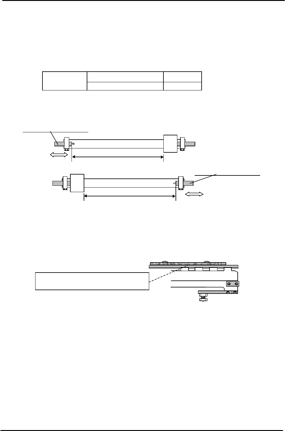
5.4 Rod-less Cylinder Stroke Check
1. Check the stroke of the IN and OUT carrier rod-less cylinders as indicated in the following
table and Fig. 6.
2. Set the stroke by adjusting the backward end shock absorber on the rod-less cylinder.
CP-643E IN carrier (Upper side) 629.0 mm
OUT carrier (Lower side) 613.5 mm
Note: Check the stroke after locking the IN & OUT carrier at their forward ends.
5.5 Conveyor Assembly Accuracy Check
1. Confirm that the PCB guide plates (2.5mm) are aligned with the upper surface of the
conveyors.
2. Confirm that the conveyor width change unit and stopper unit move smoothly by
hand.
3. Check whether the lifter plate is bent or scratched.
4. Check the maximum, minimum width and the entrance/exit of the IN & OUT conveyor.
5. The difference between the IN and OUT conveyors must be within 0.2mm. Change the
connecting chain if the value is out of tolerance.
IN Carrier Rod-less Cylinder
Out Carrier Rod-less Cylinder
In Carrier
Backward end shock absorber
Out Carrier
Backward end shock absorber
Figure 6
The Pcb guide plate and the inside surface
of the In/Out conveyor should be aligned.
Figure 7
FK-9F98-05 CP-643E Training Text for Service Engineers
Edition 5.0 Chapter 5. Loader and Conveyor Adjustment [4/28]
Fuji Machine Mfg. Co., Ltd. Okazaki
SMT Equipment Quality Assurance Dept.
Technical Support Div. Section No.2
5-
4
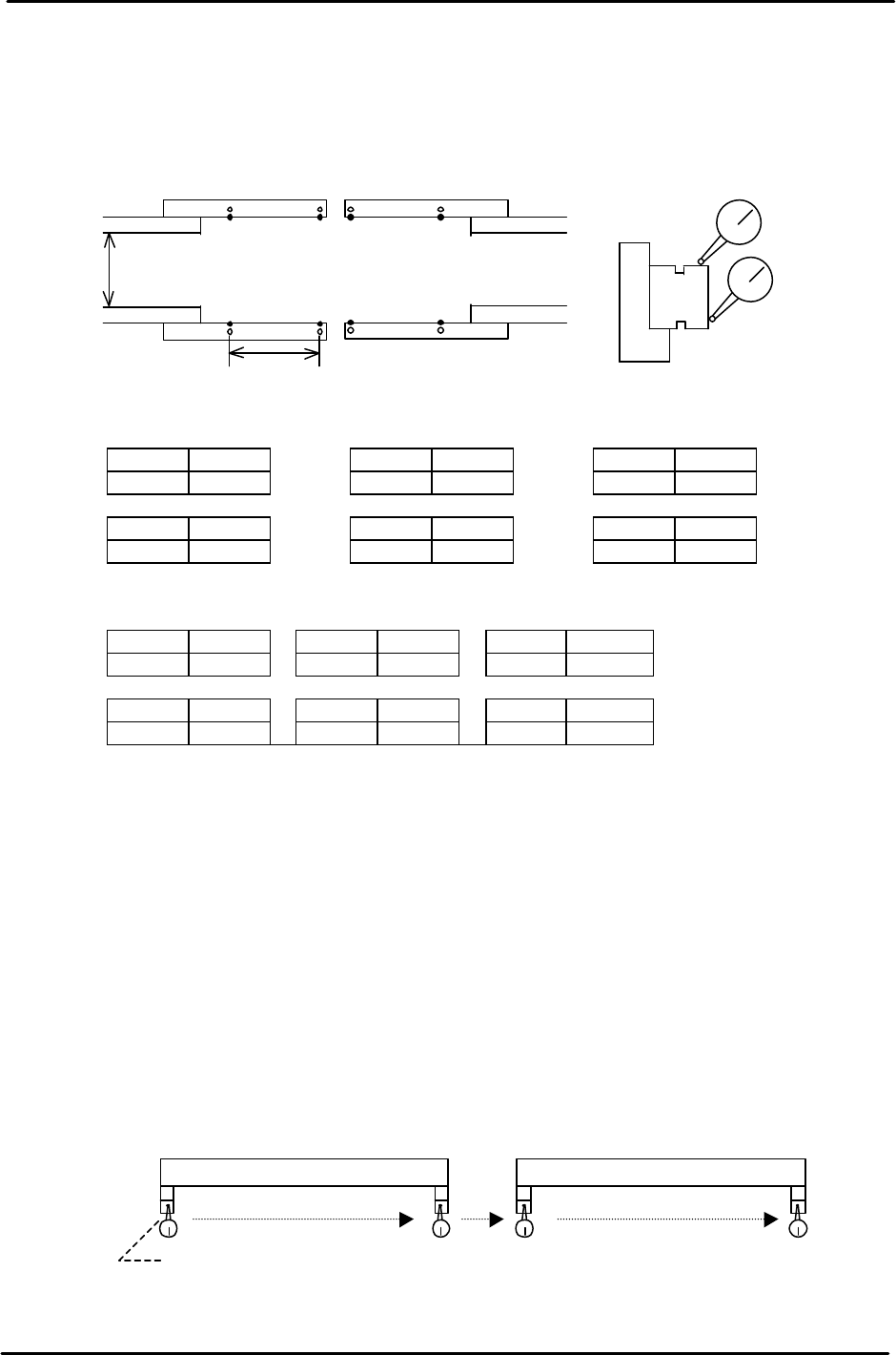
5.6 Carrier Accuracy Check
1. Set a dial indicator on the XY Table. Check the parallelism and height of the reference and
adjustable side LM guides at the positions indicated in Fig. 8.
<Parallelism> should be less than +/-0.10mm (from the zero reference position)
A B A’ B’ A A’
0 0 0
C D C’ D’ C C’
0 0 0
<Height> should be less than +/-0.20mm (from the zero reference position)
A-A’, C-C’ should be less than 0.15mm)
A B A’ B’ A A’
0 0 0
C D C’ D’ C C’
0 0 0
5.7 Joint Plate Alignment
Joint plates mounted on the In/Out carriers, engage with the main table moveable rail when Z is
lifted to the Z Load position. (Keeping the carriers and main table moveable rail aligned)
1. Check the position of the IN & OUT carrier width adjustment joint. The standard joint spacer is
0.5mm. The spacer thickness can be changed in order to align the 4 joint plates.
Spacer thickness must be within 0.5mm +/-0.2mm. (0.3mm to 0.7mm)
2. Move the carrier to the forward end and set a dial gauge on the main table. Move the X-axis
to check the parallelism of each joint.
3. Target parallelism of the 4 joints must be within 0.1mm.
B
A’
D
B’
C’C
D’
A
400mm
<Parallelism>
<Height>
200mm
Figure 8
In Carrier Out Carrier
0 reference position
Figure 9