cp45ref.pdf - 第127页
Har dwar e T r oubleshooting 3-1 Chapter 3. Hardware T roubleshooting 3.1. Power Inspection Re a dy S w i t c h C h eck t h e fu n ctio n in g o f s wit ch Is ola ti o n S wi tc h Mai n C ircu i t B reak er Mai n St art …

Samsung Component Placer CP-45F(V)/FS Reference Manual
2-72
$fb0f %d error occurred when the PackSsaChip DB memory was cancelled.
[Problem]
S/W error
[Solution]
Please contact our C/S.
$fb10 %d error occurred when the PackChuck DB memory was cancelled.
[Problem]
S/W error
[Solution]
Please contact our C/S.
$fb11 %d error occurred when the PackCa DB memory was cancelled.
[Problem]
S/W error
[Solution]
Please contact our C/S.
$fb12 %d error occurred when the PackQa DB memory was cancelled.
[Problem]
S/W error
[Solution]
Please contact our C/S.
Hardware Troubleshooting
3-1
Chapter 3. Hardware Troubleshooting
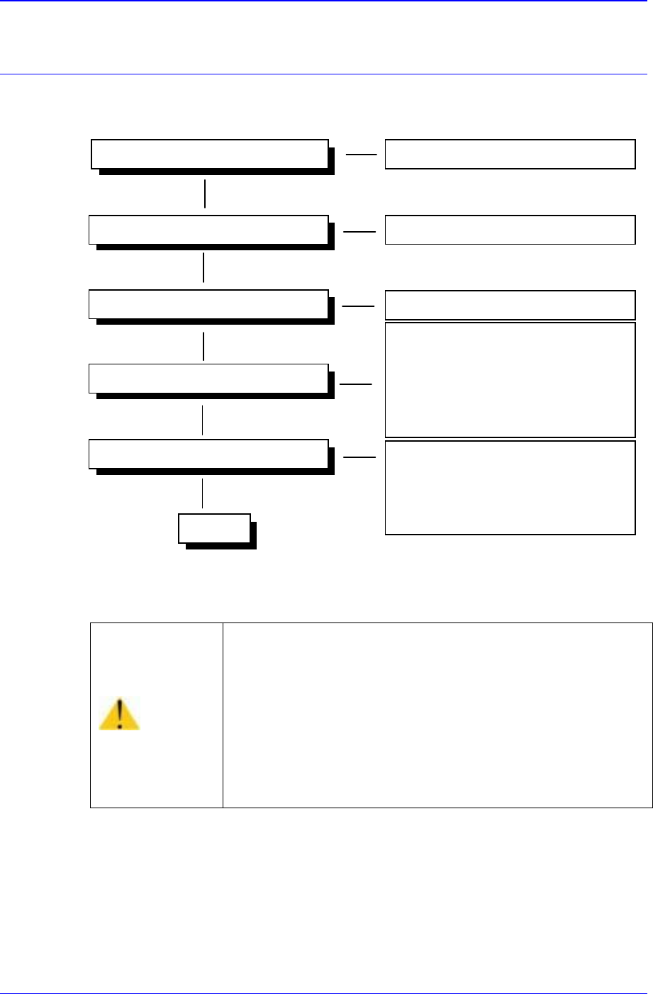
3.1. Power Inspection
Ready Switch
Check the functioning of switch
Isolation Switch
Main Circuit Breaker
Main Start Switch
- Check the EMG Front switch
- Check the EMG Rear switch
- Check the CP1 switch (TURN ON)
- Check the CP2 switch(TURN ON)
- Check the CR1-1,CR1-2,CR3 switches
Operating
- Check the CR3 relay
- Check the CONV I/F CN10
connections.
- Check the CR2-1, CR2-2 switches
Powering On (AC 220V) Check the status of power supply
Check the functioning of switch
Figure 3-1. Power Inspection
Warning
As high voltage current flows in the power supply area of
the Component Placer, if a part of human body or other
conductors touch the equipment, it could result in severe
injuries.
As charged electrons could cause electric shock for a few
minutes after the Component Placer is turned off, the
machine must be handled only by qualified personnel. And
the inspection of the machine must be done while power
supply is turned off and the power plug is completely
disconnected.
CR4
230V
Samsung Component Placer CP-45F(V)/FS Reference Manual
3-2
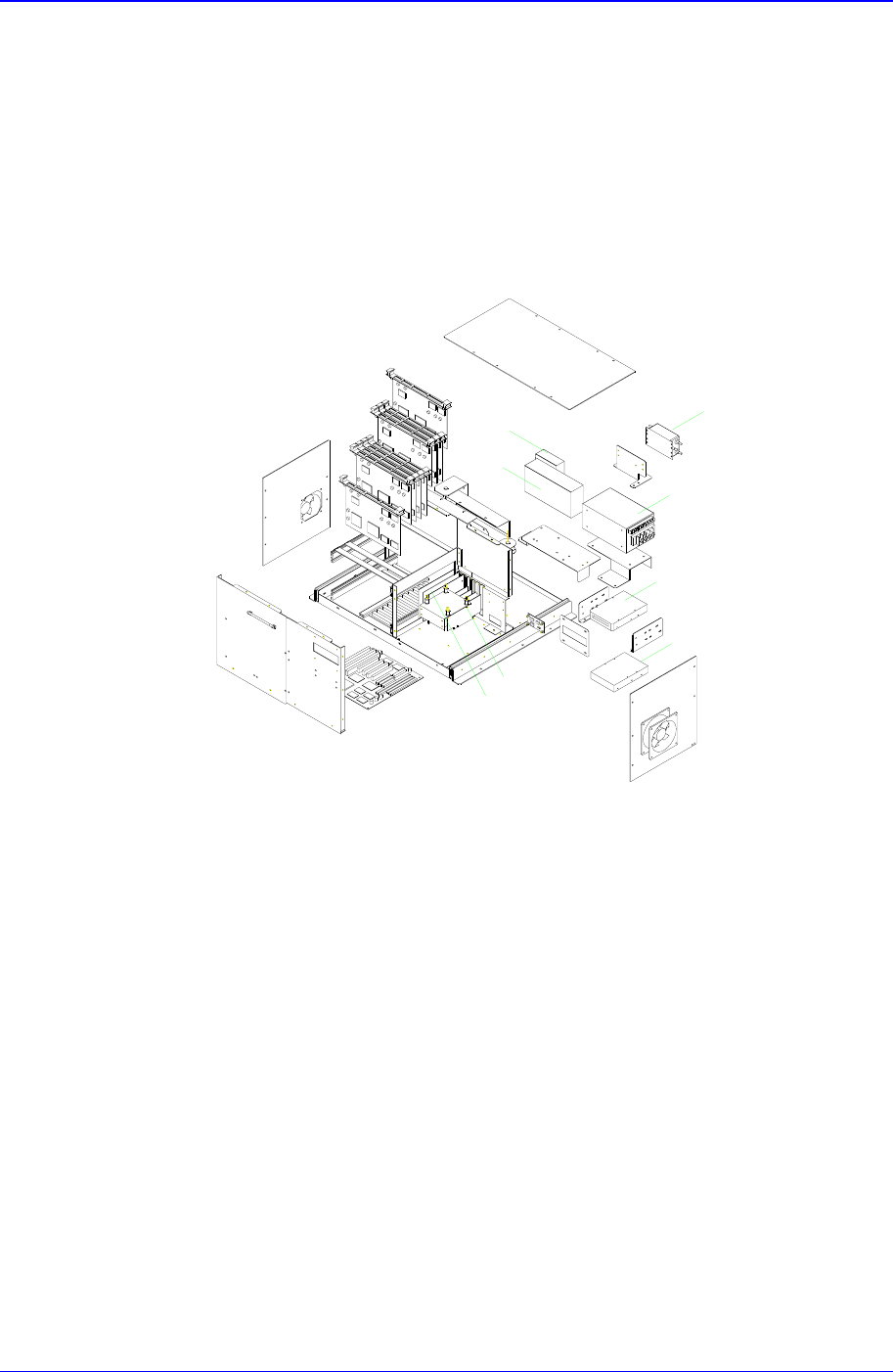
3.2. Inspection of the Controller
3.2.1. Inspection of the Controller Part
The input power (AC 110V) of the power supply controller is supplied from the output
terminal of the Noise Filter 2 (NF#2) to the PS#1, PS#2-1, PS#2-2. The PS#1, PS#2-1,
PS#2-2 are attached to the Rear Side of the Control Rack. The PS#1 supply DC 5V and
PS#2-1 supply DC +12V and PS#2-2 supply DC -12V with VME Backplane and PC.
NF#2
PS#1
PS#2-1
PS#2-2
CDROM DRIVER
HDD
VGA CARD
PC ISA I/F CARD
Figure 3-2. Control Rack
3.2.2. Inspection of the Rack Part
3.2.2.1. Inspection for PC
① Check to see if the VGA card is installed properly.
② Check to see if the HDD cables are connected properly.
③ Check to see if the FDD cables are connected properly.
④ Check to see if the CD-ROM cables are connected properly.
⑤ Check to see if the PC ISA I/F boards are assembled properly.