cp45ref.pdf - 第48页
Samsung Component Placer CP-45F(V)/FS Refer ence Manual 1-22 Figur e 1-15. Speed Contr ol V alves Solution Adjust using the speed control valve for the multi-cylinders. 1.2.6. Upward Vision Unit 1.2.6.1. Cover Glass In…
Preventive Maintenance
1-21
1.2.4. Electric Device
Inspection
Check abrasive wear in each area of the device.
Check if the machine generates errors when the switch is operated.
Check if the corresponding Input IO on the MMI IO window operates.(Emergency
Switch , Door Switch)
Check if power is disconnected when the Current Breaker is operated.
Solution
Contact our C/S center for service when severe abrasive wear is present or the
machine does not work properly.
1.2.5. Feeder Station Section
1.2.5.1. Feeder Base
Inspection
Make sure the feeder base is clear of any stray components or residue before
installing the feeders onto the feeder base.
Solution
Eliminate or remove any components or contamination on the feeder base and clean
with a soft cloth.
1.2.5.2. Adjustment of Multi Cylinder Speed
Inspection
Check to see if inadequate setting of the speed control is causing problems to feeders
operation when presenting components.
Warning
Adjusting the sensor or correcting an error while the
machine is ready could result in personal injury.
Be sure to adjust the sensor or correct an error in the stop
status (idle mode) after canceling the ready status.
Caution
Before checking abrasive wear, be sure to turn off power,
lock, and check.
Samsung Component Placer CP-45F(V)/FS Reference Manual
1-22
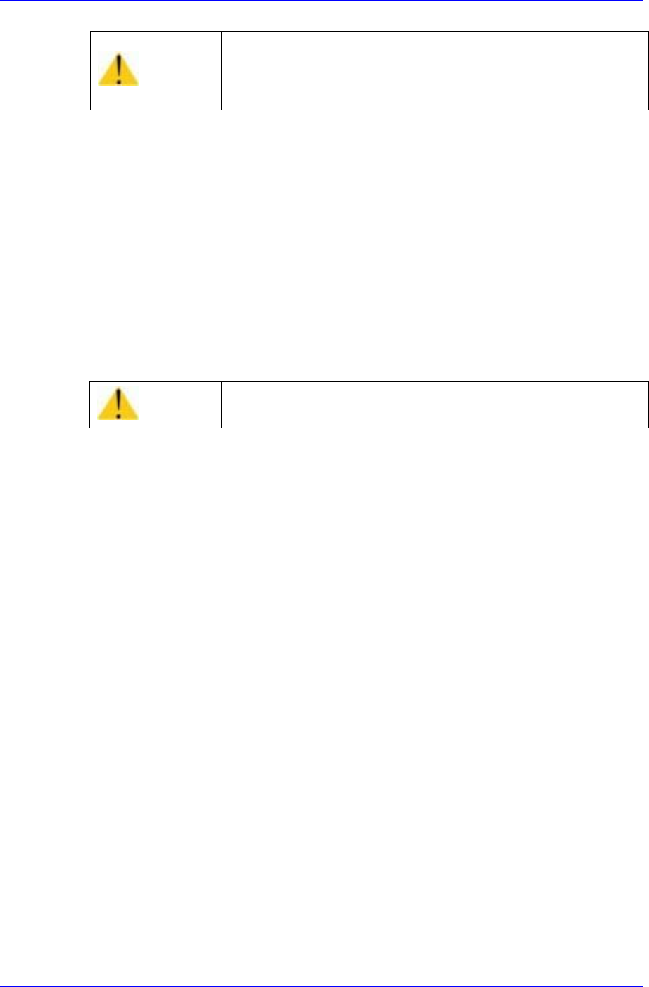
Figure 1-15. Speed Control Valves
Solution
Adjust using the speed control valve for the multi-cylinders.
1.2.6. Upward Vision Unit
1.2.6.1. Cover Glass
Inspection
Check to see if there are any dust, components or contamination on or near the cover
glass.
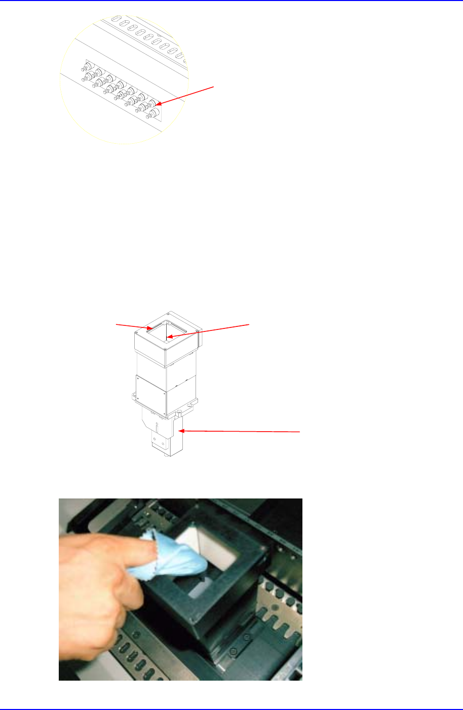
Figure 1-16. Upward Vision Unit
Solution
Speed Control Valve
LED
Cover Glass
Camera
Preventive Maintenance
1-23
Remove the LED assembly by removing the four screws to the sides of the assembly.
Clean the cover glass using a soft cloth.
Assemble the LED assembly by screwing the four screws.
1.2.6.2. Camera Lens
Inspection
Check to see if there are any dust or contamination on the camera lens.
Solution
Remove the LED assembly by removing the four screws to the sides of the assembly.
Clean the camera lens by using a soft cloth.
Assemble the LED assembly by screwing the four screws.
1.2.7. Pneumatics
1.2.7.1. Pressure Settings
Inspection
Check to see if the supplied pneumatics is appropriate for the configured pressure.
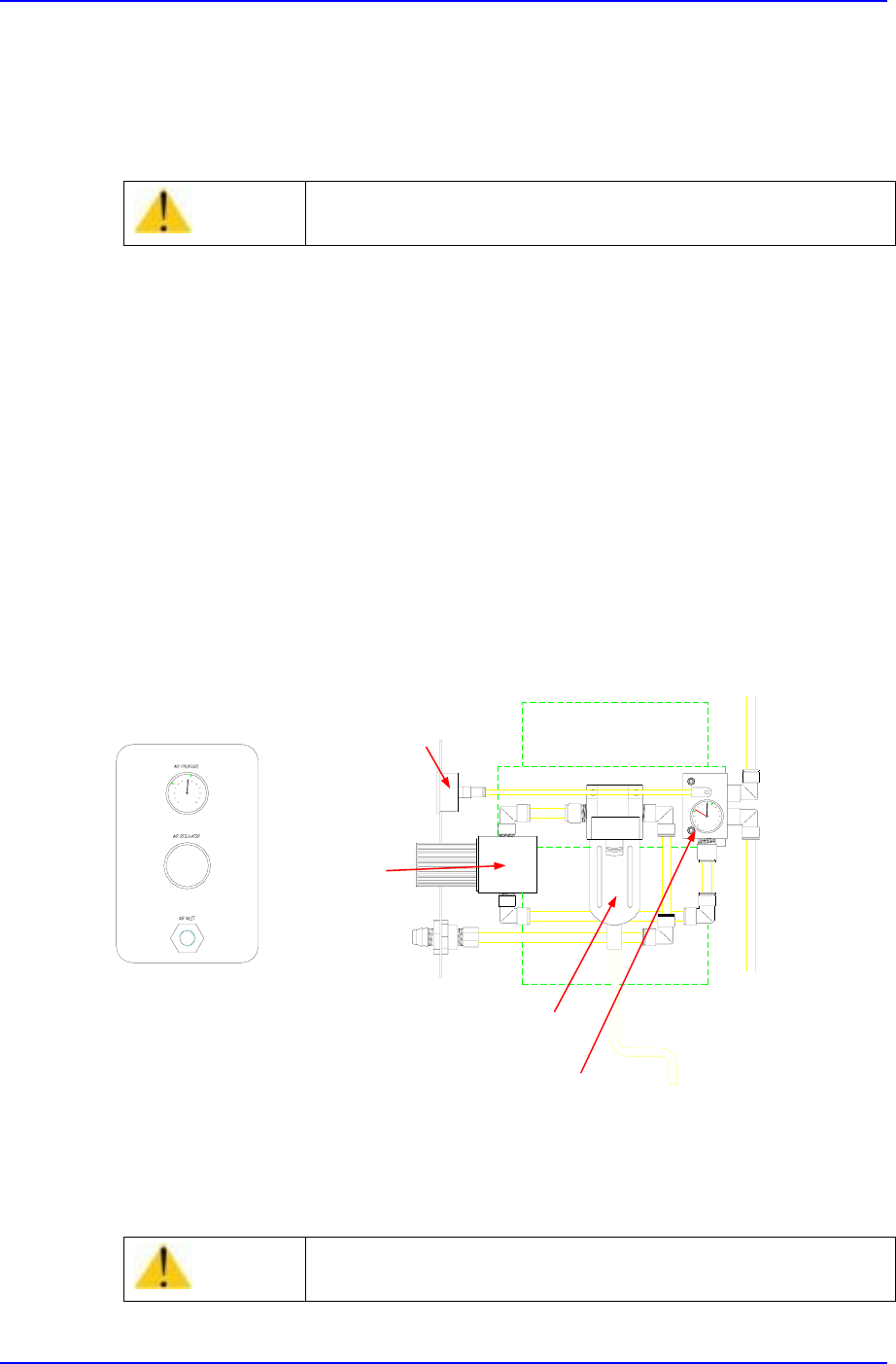
Figure 1-17. Inspection for Pneumatics
Solution
Adjust the pneumatics setting by rotating the regulator CW(Clockwise) or
CCW(Counter Clockwise).
Caution
The cover glass is fragile. Take care.
Caution
Setting the pressure incorrectly could harm the machine
performance. Set the pressure correctly.
Pressure Gauge & Auto Switch
Air Filter & Auto Drainer
Regulator
Pressure Gauge