cp45ref.pdf - 第133页
Har dwar e T r oubleshooting 3-7 3.2.2.3. Inspection of the Machine Controller Check the assembling status of RACK. Check to see if the board was properly and normally assembled. If the power is in normal, check th…
Samsung Component Placer CP-45F(V)/FS Reference Manual
3-6
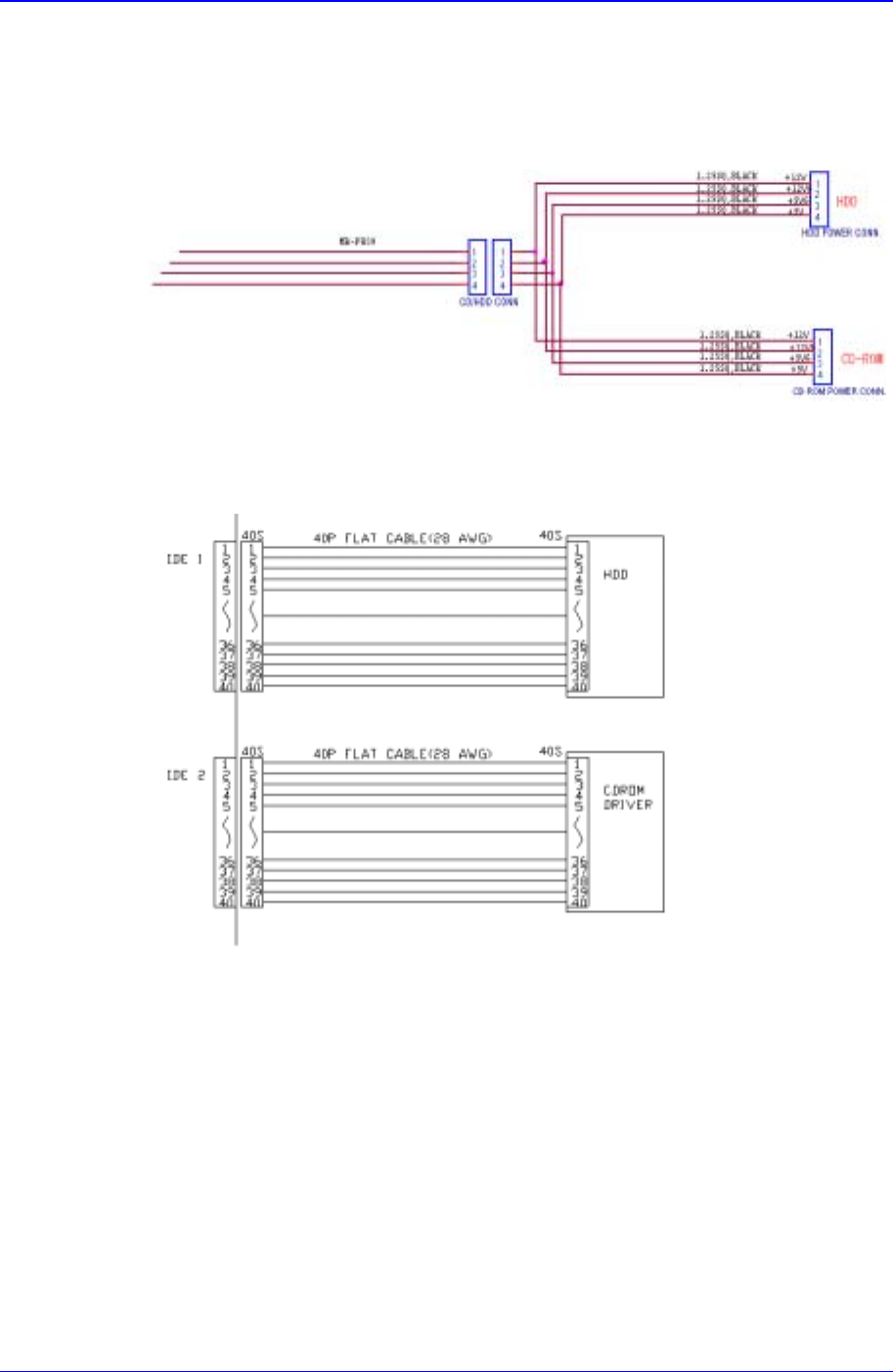
3.2.2.2.4. CD-ROM Drive
Inspection for the power supply
Check the power supply referring to the below diagram.
Figure 3-7. Inspection for the power supply of CD-ROM
Check to see if the CD-ROM cable is connected properly.
3.2.2.2.5. Keyboard
Check to see if the keyboard is connected properly.
Check the keyboard extension line.
3.2.2.2.6. Mouse
Check to see if the mouse is connected properly.
Check the mouse extension line.
Hardware Troubleshooting
3-7
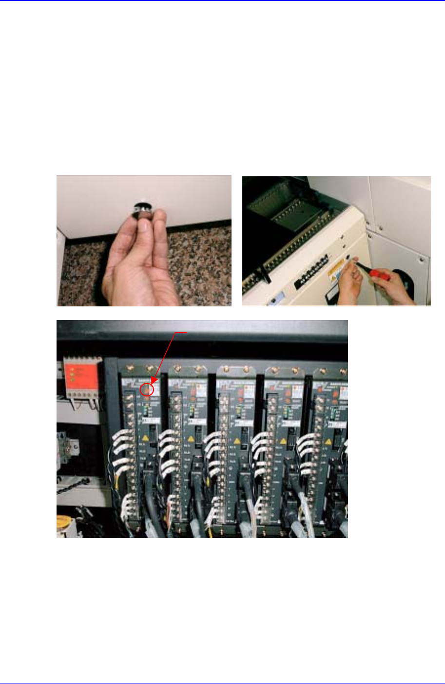
3.2.2.3. Inspection of the Machine Controller
Check the assembling status of RACK.
Check to see if the board was properly and normally assembled.
If the power is in normal, check the jumper setting.
3.3. Inspection of the Motor Part
LED
3.3.1. X-axis
Check the power of the motor drive. The LED rotates in the form of figure '8'.
Check to see if the command connector from the axis board is connected properly.
Check the status of encoder line and power supply line.
Check the connector terminal status and connection status of each drive.

Samsung Component Placer CP-45F(V)/FS Reference Manual
3-8
3.3.2. Y-axis
Check the power of the motor drive. The LED rotates in the form of figure '8'.
Check to see if the command connector from the axis board is connected properly.
Check the status of encoder line and power supply line.
Check the connector terminal status and connection status of each drive.
3.3.3. Z1~Z6, S, W axis
Check the power of the motor drive. The LED rotates in the form of figure '8'.
Check to see if the command connector from the axis board is connected properly.
Check the status of encoder line and power supply line.
Check the connector terminal status and connection status of each drive.
3.3.4. R1/2, R3/4, R5/6 axis(THETA1, THETA2, THETA3)
Check the power of the motor drive.
Check to see if the command connector from the axis board is connected properly.
The command connector is connected to the CN2, CN5, CN8 of the STEP I/F board.
Check to see if the R1/2(THETA1), R3/4(THETA2), R5/6(THETA3) from the CN3,
CN6, CN9 of the STEP I/F board is connected properly.
Check the connector terminal status and connection status of each drive.