cp45ref.pdf - 第134页
Samsung Component Placer CP-45F(V)/FS Refer ence Manual 3-8 3.3.2. Y -axis Check the power of the motor drive. The LED rotates in the form of figure '8' . Check to see if the command connector from the axis…
Hardware Troubleshooting
3-7
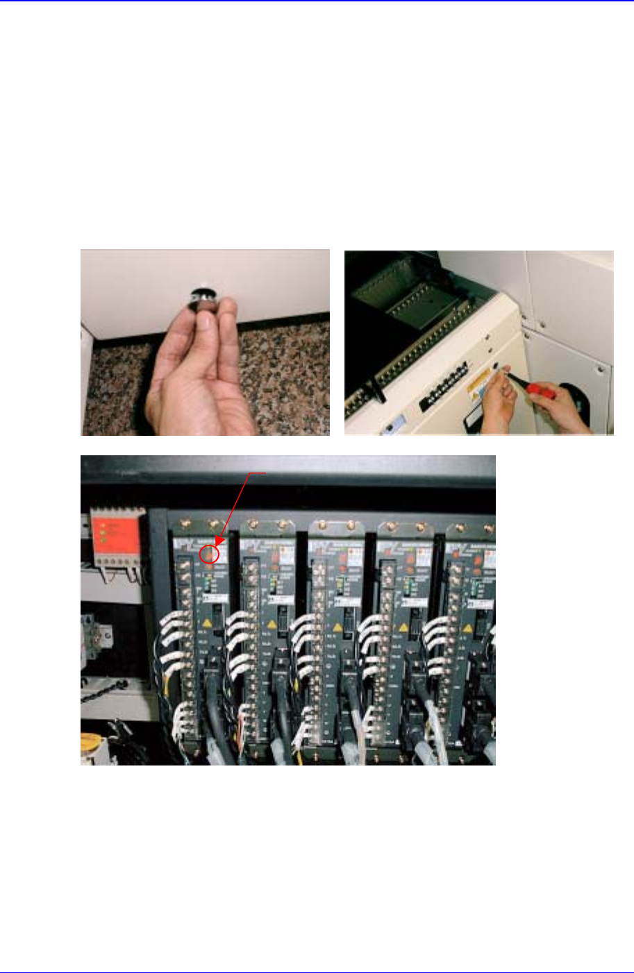
3.2.2.3. Inspection of the Machine Controller
Check the assembling status of RACK.
Check to see if the board was properly and normally assembled.
If the power is in normal, check the jumper setting.
3.3. Inspection of the Motor Part
LED
3.3.1. X-axis
Check the power of the motor drive. The LED rotates in the form of figure '8'.
Check to see if the command connector from the axis board is connected properly.
Check the status of encoder line and power supply line.
Check the connector terminal status and connection status of each drive.

Samsung Component Placer CP-45F(V)/FS Reference Manual
3-8
3.3.2. Y-axis
Check the power of the motor drive. The LED rotates in the form of figure '8'.
Check to see if the command connector from the axis board is connected properly.
Check the status of encoder line and power supply line.
Check the connector terminal status and connection status of each drive.
3.3.3. Z1~Z6, S, W axis
Check the power of the motor drive. The LED rotates in the form of figure '8'.
Check to see if the command connector from the axis board is connected properly.
Check the status of encoder line and power supply line.
Check the connector terminal status and connection status of each drive.
3.3.4. R1/2, R3/4, R5/6 axis(THETA1, THETA2, THETA3)
Check the power of the motor drive.
Check to see if the command connector from the axis board is connected properly.
The command connector is connected to the CN2, CN5, CN8 of the STEP I/F board.
Check to see if the R1/2(THETA1), R3/4(THETA2), R5/6(THETA3) from the CN3,
CN6, CN9 of the STEP I/F board is connected properly.
Check the connector terminal status and connection status of each drive.
Hardware Troubleshooting
3-9
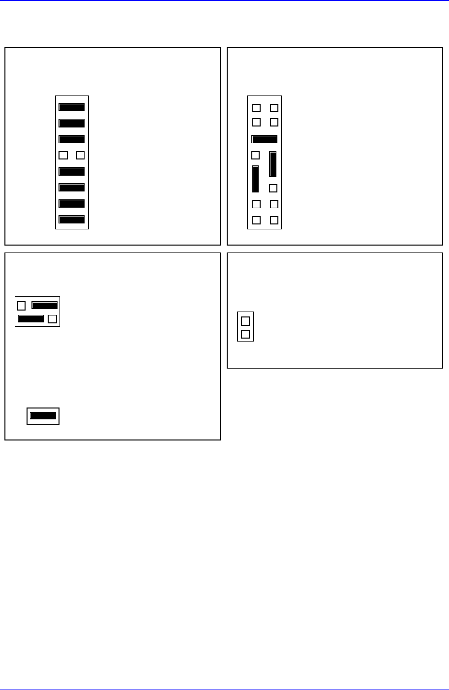
3.4. MVME162-220 Jumper Setting
J12 : 8 EPROMs = 4MB
21
15 16
J12
Configuration 3 : 512K
×
8EPROMs
J11 : EPROM booting
GPIO0
GPIO1
GPIO2
GPIO3
GPIO4
GPIO5
GPIO6
GPIO7
21
7
15 16
8
J11 User Code Installed
User-Defiinable
User-Defiinable
User-Defiinable
In=Flash; Out=EPROM
User-Defiinable
User-Defiinable
User-Defiinable
User-Defiinable
EPROMs Selected (Factory configuration)
J13 : Primary Source VMEbus +5V STBY
2
1
J13
6
5
Primary Source VMEbus +5V STBY
Secondary Source Onboard Battery
J1 : System Controller
21
J1
System Controller (Factory configuration)
J14 : SCSI terminator disabled
2
1
J14
On-Board SCSI Bus Terminat or Disabled
Figure 3-8. MVME162-220 Jumper Setting