UV-9+Cure+Module+7269348_B+Manual.pdf - 第108页
6.5.5 Close d Loop Calibration Proc edure NOTE You must have Maint enance Access level to per form this procedur e. Tools and Materials Needed: • Power Puck or other UV Measuring Device (Radiometer) NOTE Perform all …
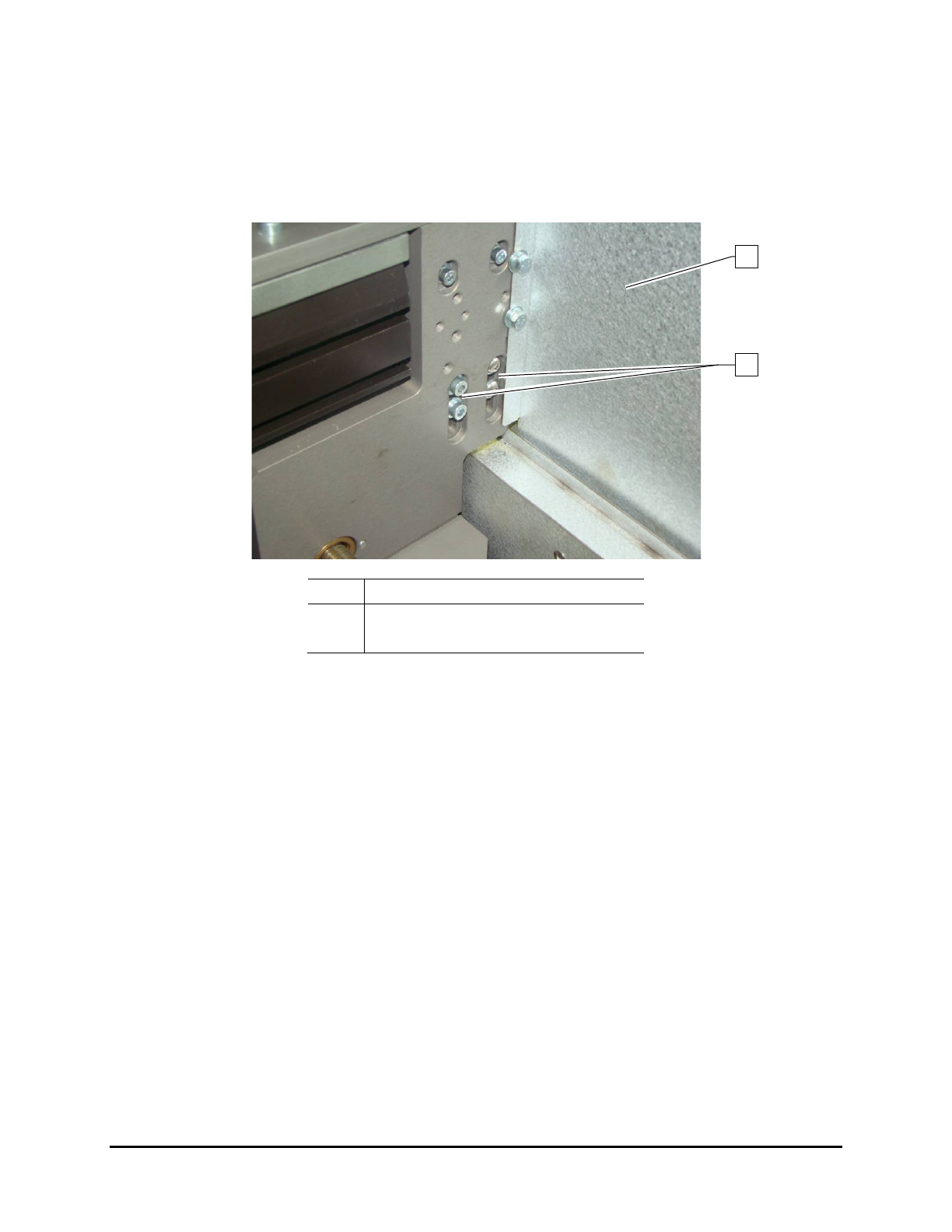
6.5.4.2 Rear Rail Chain Tension Adjustment (UV-9 Version 1 Only)
To adjust the rear rail chain tension:
1. Open the upper rear cover.
2. Remove the left UV radiation trap (Figure 4-5).
Item Description
1 Sliding Shutter
2 Chain Tensioner Screws
Figure 6-16 Rear Rail Chain Tension Adjustment
NOTE Do not remove the sliding shutter.
3. From the back, loosen the four (4) screws securing the chain tensioner (Figure 6-16).
4. From outside, tighten the screw underneath the tensioner (Figure 6-15).
5. Push the sprocket down and tighten the four (4) screws to secure the tensioner.
6. Loosen the screw underneath the tensioner so the tensioner spring can work.
7. Replace the left-side UV radiation trap and close the upper rear cover.
1
2
Maintenance 6-13
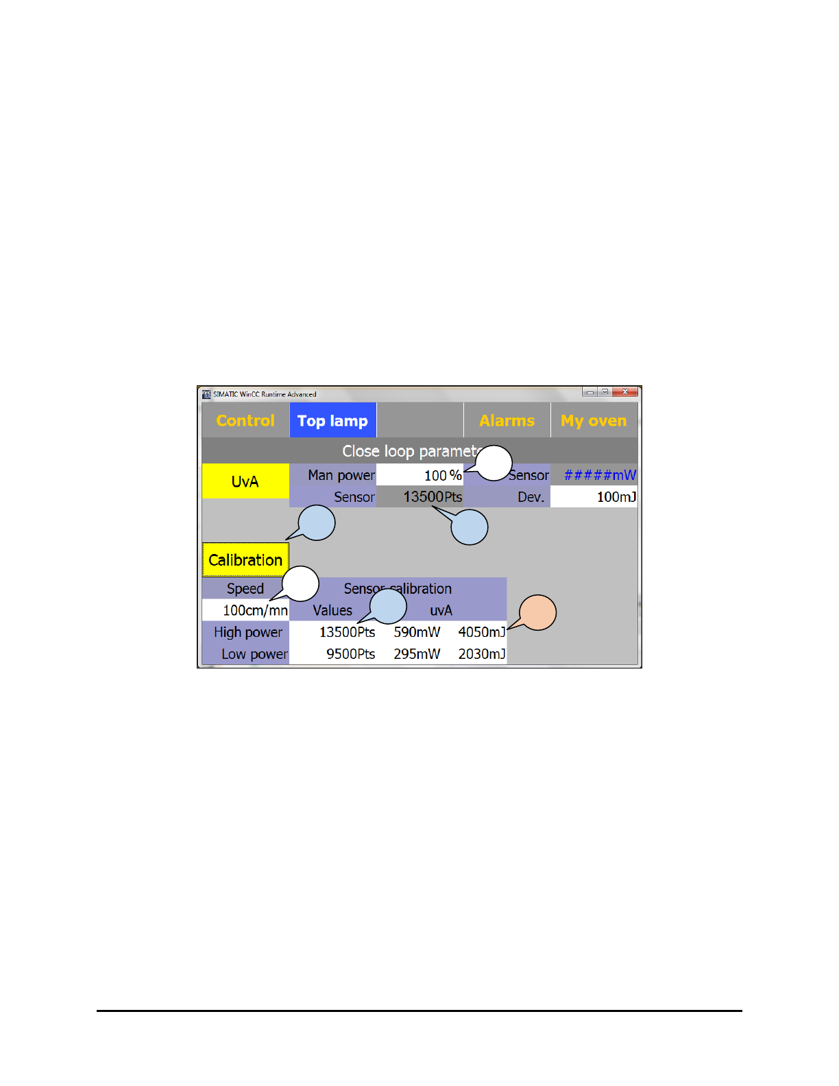
6.5.5 Closed Loop Calibration Procedure
NOTE You must have Maintenance Access level to perform this procedure.
Tools and Materials Needed:
• Power Puck or other UV Measuring Device (Radiometer)
NOTE Perform all measurements with a cold UV measuring device; ideally the temperature
should be under 25 °C. UV measuring devices are sensitive to humidity, therefore it is
recommended that you store and use within a constant humidity range.
The accuracy of a Power Puck is + /- 10% , typically + /- 5%.
To perform the closed loop calibration:
1. Select
Top Lamp > Parameters > Manu to put the oven in manual mode.
2. Click on
Calibration (Figure 6-17).
Figure 6-17 Closed Loop Parameters Screen – High Power
3. Enter the conveyor speed.
The speed entered in this screen is used only for calibration and calculation; it does not
set the actual conveyor speed.
4. Set
Man Power to 100% (this control box is an active control box; it sets the value).
In case of a cold start, allow the oven to warm-up for 15 minutes before calibrating.
5. Copy the Sensor read value in the Sensor Calibration High Power field.
The UV sensor resolution varies per machine as they are individually validated. The
read value in terms of points represents the analog input value at the PLC.
6. Position the UV puck on a flat carrier or surface and point the puck sensor toward the lamp
top or bottom.
Make sure the puck is at the same height as the substrate to get an accurate UV
measurement.
3
2
4
5
5
7
6-14 Maintenance
7. Perform a UV measurement and enter the UVA results; intensity (mW/cm²) and dose
(mJ/cm²) in the High Power Value and UVA fields.
Calibration at 100% power is now complete.
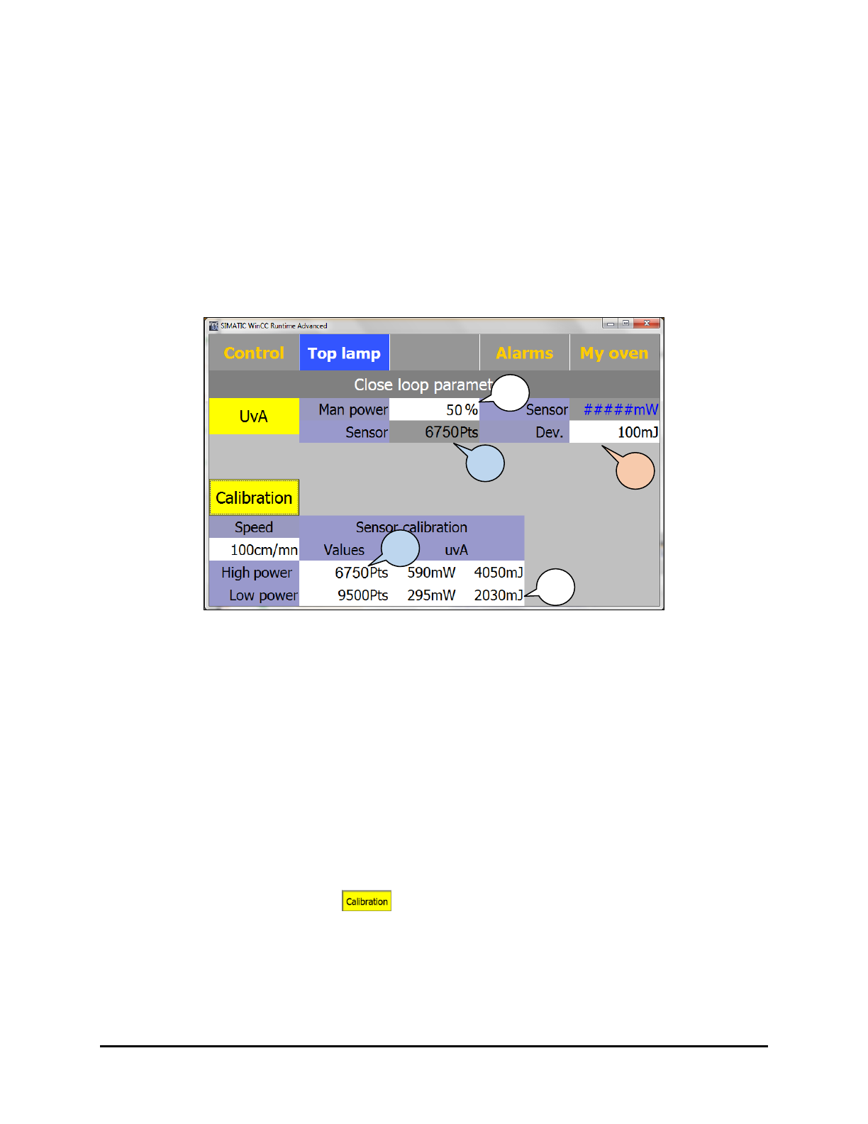
8. Set
Man Power to 50% (Figure 6-18).
This control box is an active control box; it sets the value.
Wait 15 minutes for temperature stabilization before calibrating.
9. Copy the Sensor read value in the Sensor Calibration Low Power input textbox.
The UV sensor resolution varies per machine as they are individually validated. The
read value in terms of points represents the analog input value at the PLC.
Figure 6-18 Closed Loop Parameters Screen – Low Power
10. Position the UV puck on a flat carrier or surface and point the puck sensor toward the lamp
top or bottom.
Make sure the puck is at the same height as the substrate to get an accurate UV
measurement.
11. Perform a UV measurement and enter the UVA results; intensity (mW/cm²) and dose
(mJ/cm²) in the Low Power field.
Calibration at 50% power is now complete.
12. Set the
Dev (deviation or tolerance) on the UV sensor reading. The standard value is
100 mJ, which means that the UV-9 is giving the UV process free as soon 100 mJ
variation is measured from the set point.
13. When finished, click on
again to activate the SMEMA signals (the background
should be gray instead of yellow).
14. Use the UV puck to validate the calibration by comparing the measured dose and intensity
values with the UV-9 values on the Top/Bottom Lamp Parameters screen.
12
8
9
9
11
Maintenance 6-15