UV-9+Cure+Module+7269348_B+Manual.pdf - 第18页
1.9.2 Rear View Features Figure 1-2 and Table 1-4 d escribe the rear exterio r features of the UV - 9 Cure Module. Figure 1-2 Rear View 1 3 2 4 5 6 1-6 Introduction
Table 1-3 Front View Features
Item
Name
Description
1
Curing Chamber
Hood
Provides access to the conveyor and associated mechanical and electrical
connections. The Hood is opened via a keyed lock.
2
ON Button
(Green)
The ON button powers on the UV-9 Cure Module. Note: The ON button
DOES NOT turn on the oven.
3
Start/Stop Button
(Black)
The Start/Stop button turns the oven on and off. To start the over, press
the black button for one (1) second. To stop the oven, press the black
button for five (5) seconds.
4 Door Lock
A keyed door lock restricts access to the electrical components located in
the electronics enclosure.
5
Electronics
Enclosure Door
To gain access to UV-9 Cure Module electronics, make sure the Main
Power Switch is in the OFF (I) position, and unlock the door with the key
provided.
6 E-Stop Button
Cuts power to all system components. See 2.10 Emergency Shutdown for
detailed information.
7 Levelers
The feet of the UV-9 Cure Module. They are adjusted during installation
and should not need attention unless the cure module is moved to a new
location. See 3.7 Leveling the UV-9 Cure Module for more information.
8 Light Beacon
Visually indicates UV-9 Cure Module operating status. It has green,
orange, and red status indicator lamps. See 2.13.3 Light Beacon for lamp
color definitions.
Introduction 1-5
1.9.2 Rear View Features
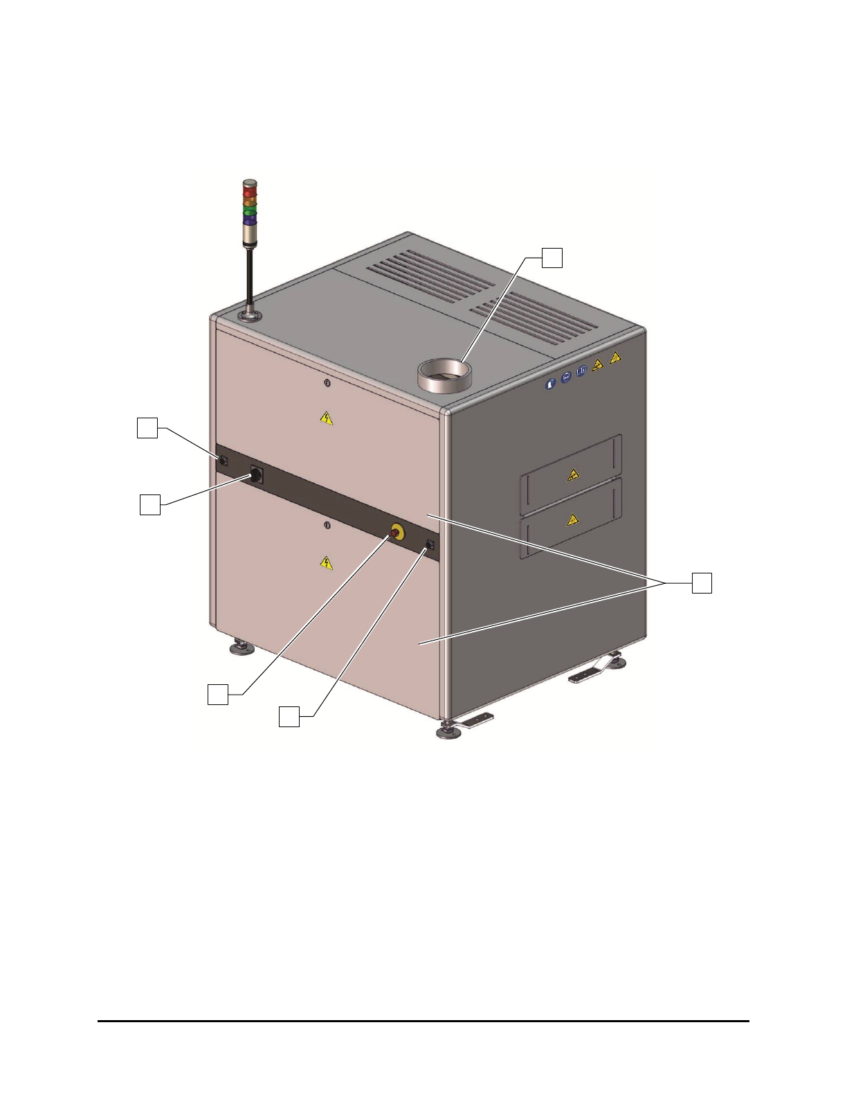
Figure 1-2 and Table 1-4 describe the rear exterior features of the UV-9 Cure Module.
Figure 1-2 Rear View
1
3
2
4
5
6
1-6 Introduction
Table 1-4 Rear View Features
Item
Name
Description
1 Exhaust Port
The 152.4 mm (6 in) diameter exhaust port attaches to the ducting of the
facility ventilation system. Heat and hazardous vapors produced in the
curing process are safely removed from the UV-9 Cure Module.
2
Rear Enclosure
Access Panels
The rear access panel provides access to the UV lamp power supply
network and main power electrical connections.
3
Upstream
SMEMA Port
The upstream SMEMA connector allows for communication between the
UV-9 Cure Module and an upstream machine.
4 E-Stop Button
Cuts power to all system components. See 2.10 Emergency Shutdown for
detailed information.
5
Main Power
Switch
The Main Power Switch is mechanically connected to the Main Circuit
Breaker in the electronics enclosure. A flange on the switch housing allows it
to be locked in the OFF (I) position during servicing. Switching off the Main
Power Switch cuts power to all system components.
6
Downstream
SMEMA Port
The downstream SMEMA connector allows for communication between the
UV-9 Cure Module and a downstream machine.
Introduction 1-7