UV-9+Cure+Module+7269348_B+Manual.pdf - 第16页
1.9 System Illustrations The figures in this section sho w views and features o f the cure module. Callo uts locate major componen ts and switches seen in each illustration . System features are sho wn in Figure 1-1 and …

1.7 Training
Nordson ASYMTEK offers quality training for our curing platforms, valves, software, and applications
both on and off-site. The labs at our Carlsbad, California, USA corporate location are dedicated to
providing a specialized course of instruction for our customer's specific needs. With the assortment of
tools available in our labs, we are able to provide a better learning experience overall. Students will
rebuild machine subassemblies, troubleshoot real problems, and learn a variety of setup techniques. In
addition, your machine's operability and production are not disturbed due to class usage.
1.7.1 Student Certification
Upon successful completion of the training course, the student is issued a Certificate of Completion.
1.7.2 Student Registration
Students can register for training at the Nordson ASYMTEK website www.nordsonasymtek.com or call
1-800-ASYMTEK to request information or to register for training.
1.8 Conveyor
The UV 9 Cure Module is equipped with a SMEMA-compatible chain conveyor. The conveyor consists
of a drive motor, two heat-resistant poly-acetyl chains, and two metallic rails with attached sprockets and
guides. Conveyor operation during a production run is automatic.
1.8.1 Theory of Operation
The conveyor and associated components control workpiece movement through the UV-9 Cure Module
during a production run.
Two retro-reflective sensors, mounted on the front conveyor rail near the UV-9 Cure Module entrance
and exit ports, monitor the progress of workpieces through the curing zone. Board presence is reported to
the system’s internal PLC which expects to see a workpiece enter and exit the cure module. When the
board enters the oven, a counter is started and the PLC tracks the time to reach the second sensor
(function of the distance between the 2 sensors and the speed of the conveyor). If the counter reaches the
preset count before the workpiece is sensed by the exit sensor, the
Traffic Fault LED on the operator’s
control panel illuminates, the cure module goes into
Pause mode, and the light beacon displays the red
light.
1.8.2 Set-up and Adjustment
The conveyor is configured for your particular application at the Nordson ASYMTEK factory. Any
modifications to the system set-up should be performed by trained service technicians only. Conveyor rail
width is adjustable. See Section 4 – Adjustments for detailed procedures.
Introduction 1-3
1.9 System Illustrations
The figures in this section show views and features of the cure module. Callouts locate major components
and switches seen in each illustration. System features are shown in Figure 1-1 and Figure 1-2.
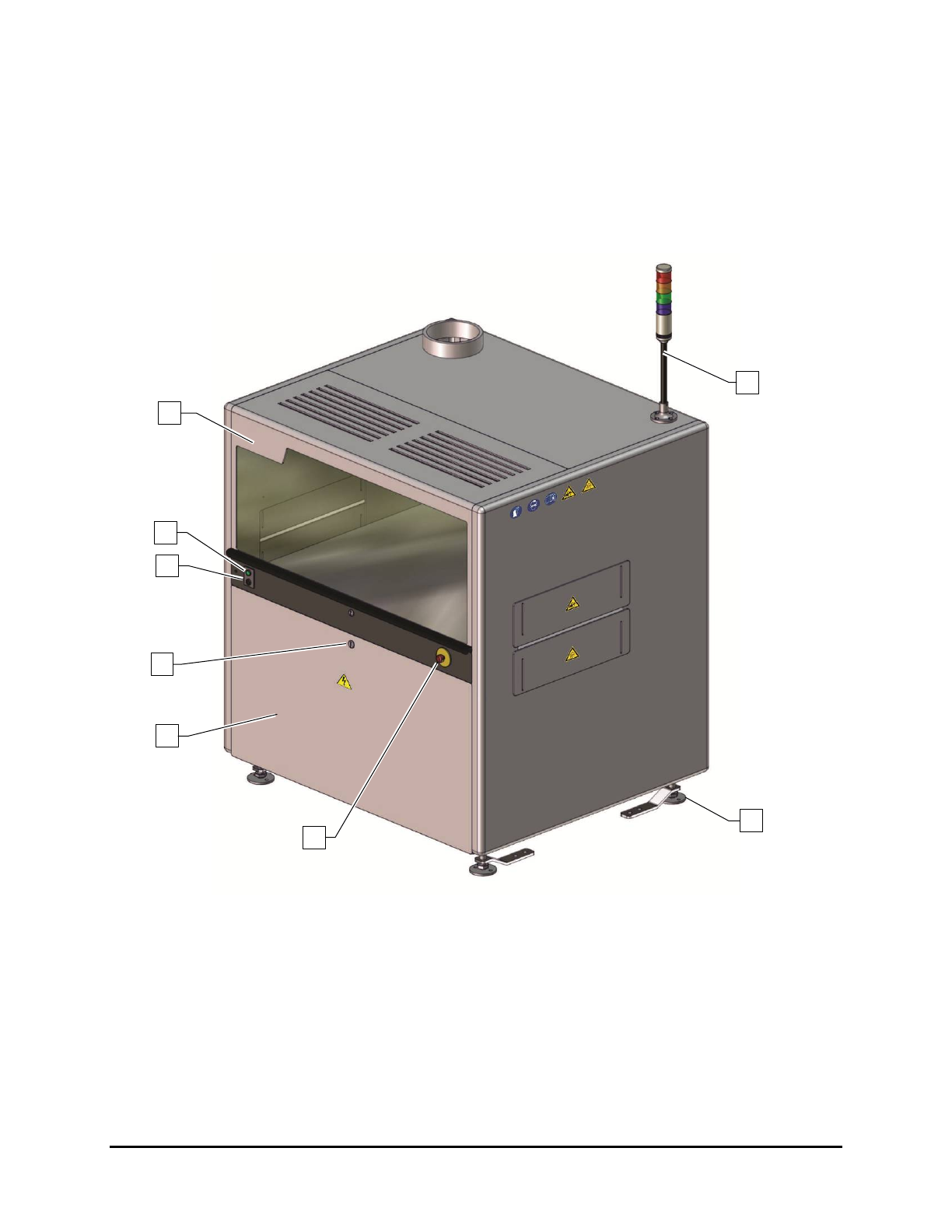
1.9.1 Front View Features
Figure 1-1 and Table 1-3 describe the front exterior features of the UV-9 Cure Module.
Figure 1-1 Front View
8
7
6
2
4
5
1
3
1-4 Introduction
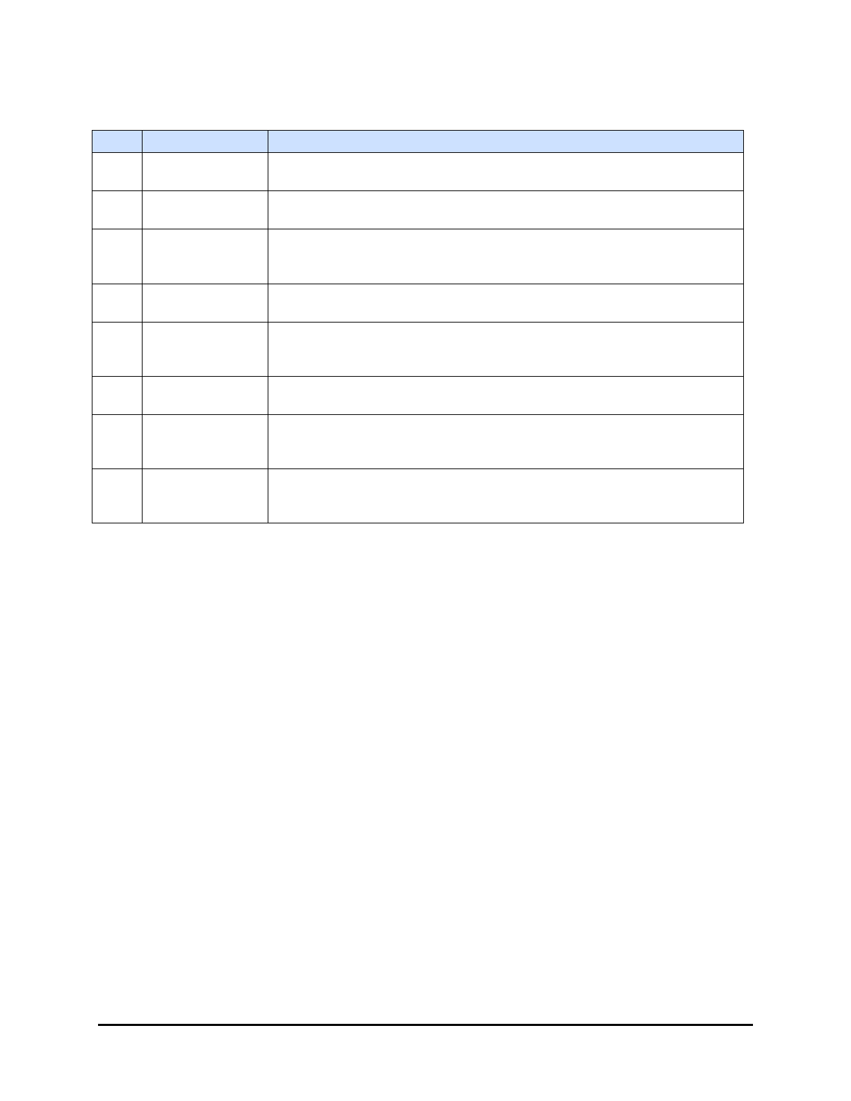
Table 1-3 Front View Features
Item
Name
Description
1
Curing Chamber
Hood
Provides access to the conveyor and associated mechanical and electrical
connections. The Hood is opened via a keyed lock.
2
ON Button
(Green)
The ON button powers on the UV-9 Cure Module. Note: The ON button
DOES NOT turn on the oven.
3
Start/Stop Button
(Black)
The Start/Stop button turns the oven on and off. To start the over, press
the black button for one (1) second. To stop the oven, press the black
button for five (5) seconds.
4 Door Lock
A keyed door lock restricts access to the electrical components located in
the electronics enclosure.
5
Electronics
Enclosure Door
To gain access to UV-9 Cure Module electronics, make sure the Main
Power Switch is in the OFF (I) position, and unlock the door with the key
provided.
6 E-Stop Button
Cuts power to all system components. See 2.10 Emergency Shutdown for
detailed information.
7 Levelers
The feet of the UV-9 Cure Module. They are adjusted during installation
and should not need attention unless the cure module is moved to a new
location. See 3.7 Leveling the UV-9 Cure Module for more information.
8 Light Beacon
Visually indicates UV-9 Cure Module operating status. It has green,
orange, and red status indicator lamps. See 2.13.3 Light Beacon for lamp
color definitions.
Introduction 1-5