UV-9+Cure+Module+7269348_B+Manual.pdf - 第46页
3.12 Pneumatic Connection (Shutte r Option ) If the UV - 9 Cure Module is equippe d with shutter (entrance and/or exit) , it m ust be connect ed to the pneumatic system. 1. Pneumatic specificatio ns are listed below: • A…
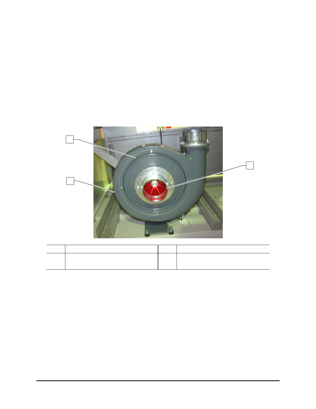
3.11.1 Exhaust Fan Rotation Direction
To check the rotation direction:
1. Disconnect the blower hose to see the impeller (Figure 3-9).
2. Turn the Main Power Switch located at the back of the UV Cure Module to the
ON (l)
position.
3. Press the relay KM3 inside the electrical cabinet.
4. Verify that rotation matches the direction of the arrow.
5. After confirming proper rotation, turn the Main Power Switch to the
OFF position (0).
6. Reconnect the blower hose.
Item
Description
Item
Description
1 Exhaust Pump 3 Impeller
2 Direction of Rotation Arrow
Figure 3-9 Exhaust Pump
1
2
3
Installation 3-9
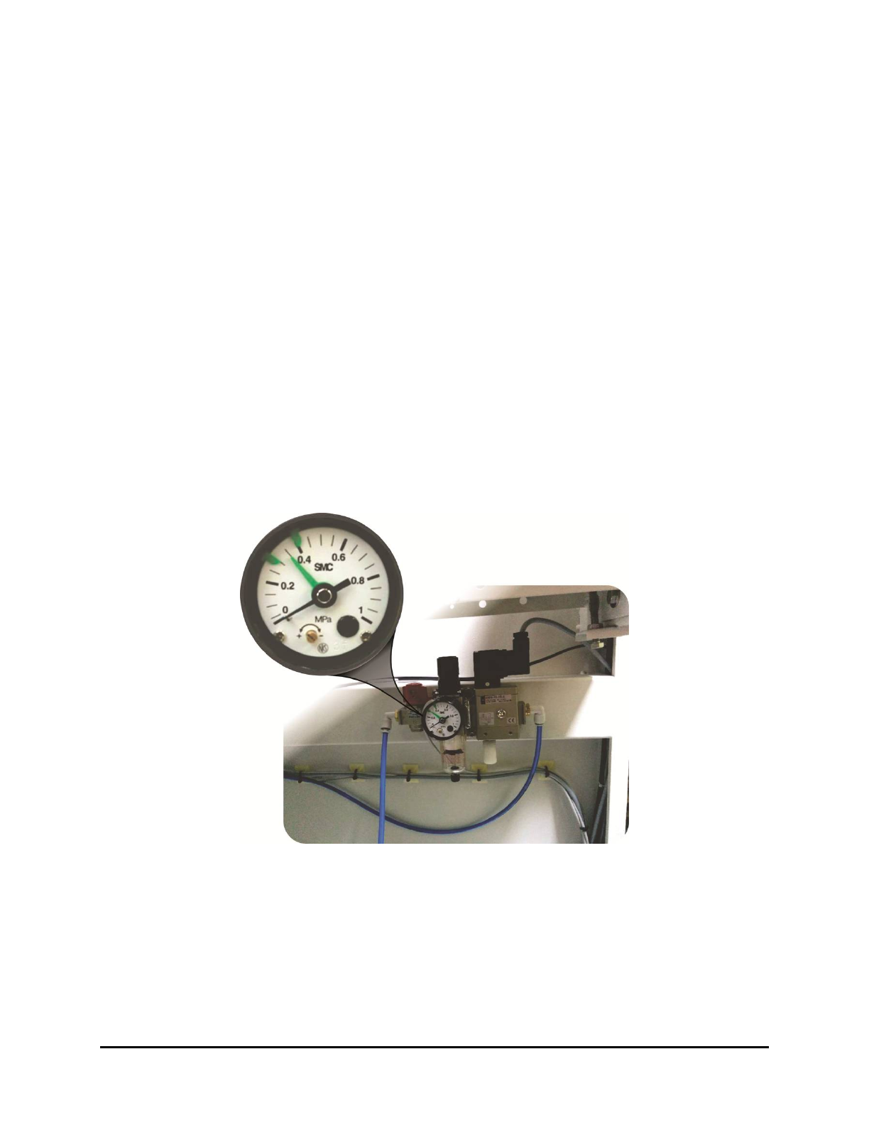
3.12 Pneumatic Connection (Shutter Option)
If the UV-9 Cure Module is equipped with shutter (entrance and/or exit), it must be connected to the
pneumatic system.
1. Pneumatic specifications are listed below:
• Air pressure: 0.6 MPa (87 psi)
• Connecting pipe: 6 mm
• Consumption: < 0.02 m
3/H
2. Set the pressure regulator to 0 MPa.
3. Verify the facility air pressure is off (0).
4. Connect the facility air hose to the pressure regulator.
5. If not already connected, connect the air hose to the facility air supply.
6. Set the facility air supply to 0.6 MPa (97 psi).
7. Set the pressure regulator to 0.35 MPa (50 psi).
The “green” needle is for the pressure sensor; the black needle is the actual set pressure
with the filter regulator.
Figure 3-10 Shutter Pneumatics
3.13 Post-installation Functional Testing
After installation has been completed, the Nordson ASYMTEK service technician will perform all testing
necessary to ensure quality performance of your UV-9 Cure Module.
NOTE As a precaution, the UV lamp is not pre-installed at the factory. It will be installed on-site
by the Nordson ASYMTEK technician. See 6.5.2 UV Lamp Replacement.
3-10 Installation
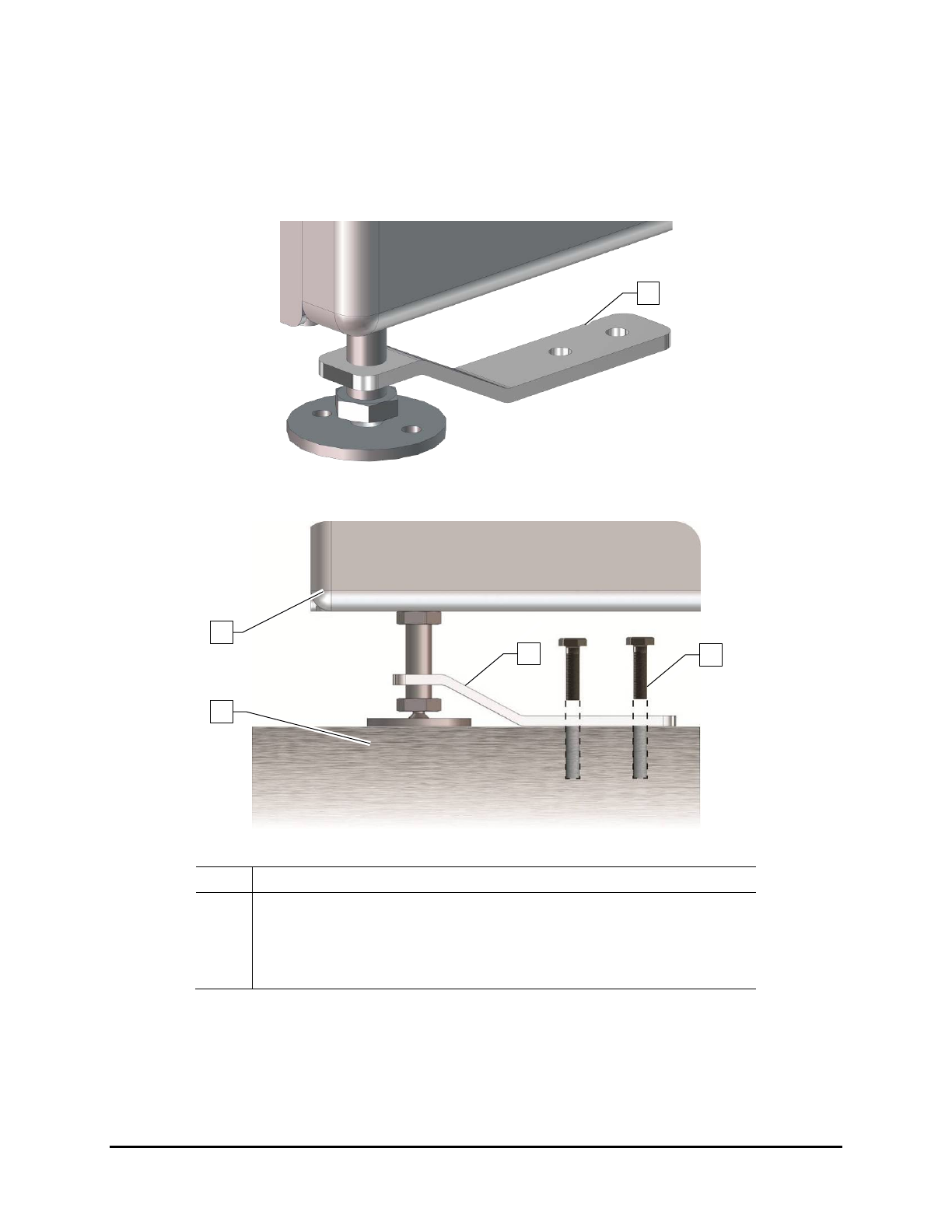
3.14 Anchoring the Oven
To prevent movement that could cause injury to personnel and damage to the cure module and facility,
each cure module leveler (foot) should be anchored to the floor with two bolts (Figure 3-11 and
Figure 3-12). The anchor joint (the point between each anchor bolt and the floor) must be able to
withstand at least 220 lbs (100 kg) of pullout force.
Figure 3-11 Seismic Brackets
Item Description
1 Cure Module
2 Leveler
3 Seismic Bracket
4 Anchor Bolts
Figure 3-12 Anchoring the UV-9 Cure Module
2
1
3
4
3
Installation 3-11