UV-9+Cure+Module+7269348_B+Manual.pdf - 第77页
5.7.3 Ala rms Screen The Alarm s screen display s the active alarms ( Figure 5- 16 ). Name Description Alarm Ack Button Select the Alarm Ack butt on, after fixing the def ect, to acknowledge the alarm condition and reset…
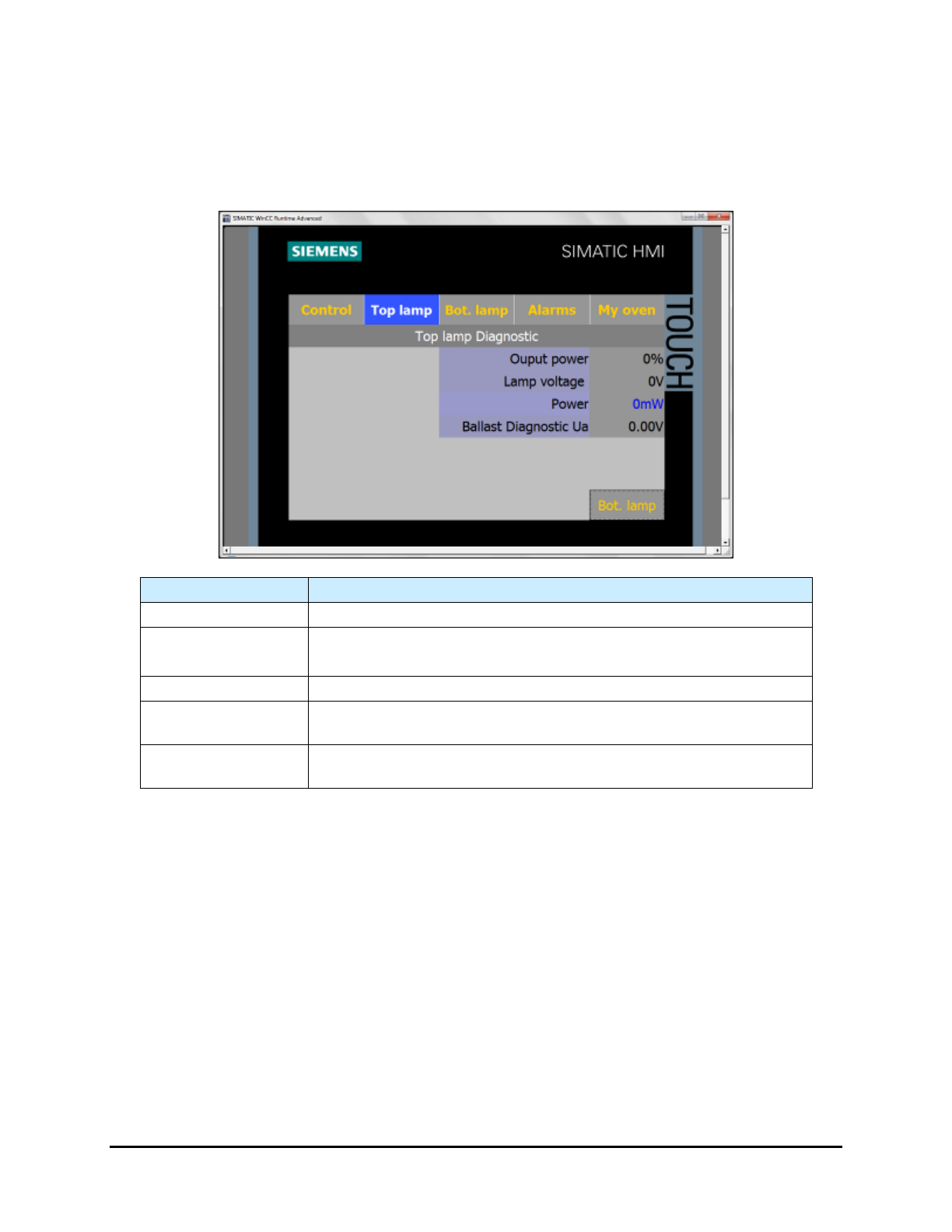
5.7.2.4 Diagnostic Screen
The Lamp Diagnostic screen (Figure 5-15) provides valuable information when troubleshooting the
system.
NOTE Only viewable in Maintenance and Admin Mode.
Name
Description
Output Power
Displays the current output power in % applied to the lamp.
Lamp Voltage
Displays the voltage applied to the UV lamp.
The background color is orange when the lamp is too cold (No UV).
Power
Displays the power in mw/cm² seen by the sensor (close loop).
Ballast Diagnostic
Ua
Displays the voltage (vdc) sent by the ballast to the PLC.
BotLamp / TopLamp
Button
Select BotLamp/TopLamp to toggle between the Bottom Lamp
Diagnostic screen and the Top Lamp Diagnostic screen.
Figure 5-15 Lamp Diagnostic Screen (Top Lamp shown)
5-14 Operation
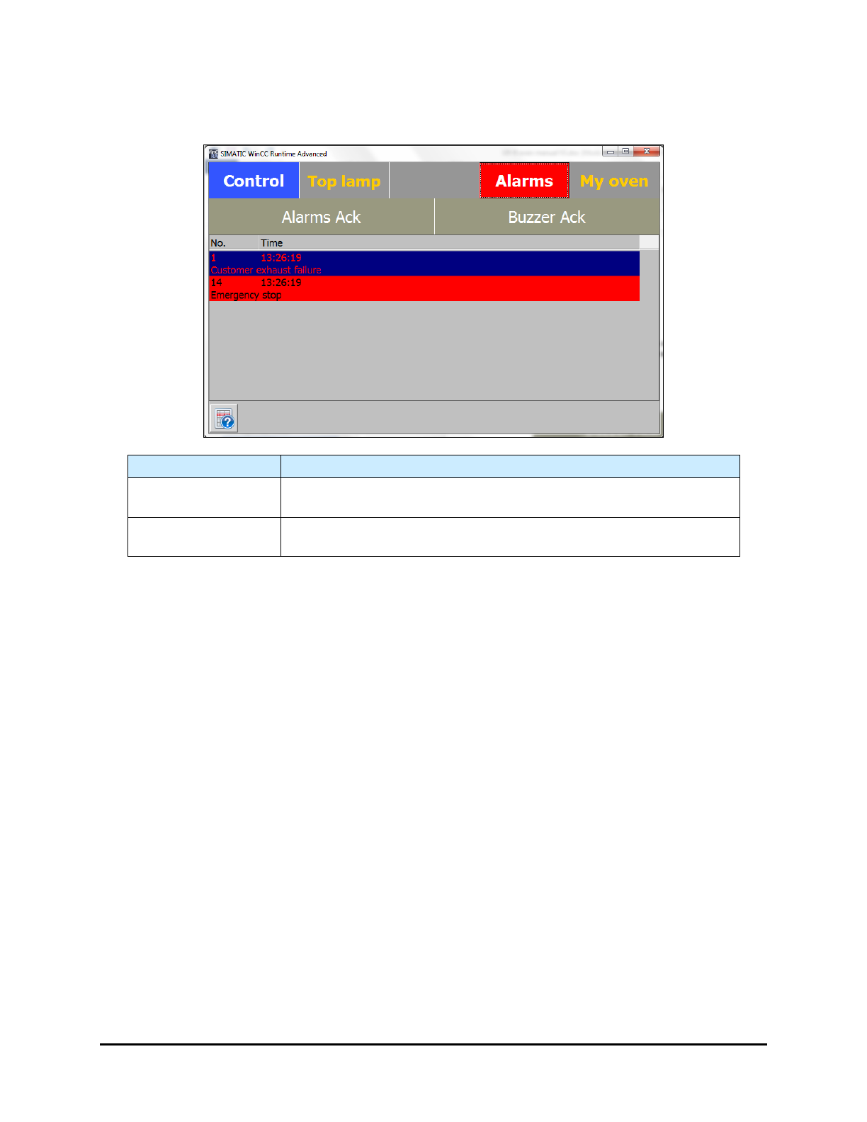
5.7.3 Alarms Screen
The Alarms screen displays the active alarms (Figure 5-16).
Name Description
Alarm Ack Button
Select the Alarm Ack button, after fixing the defect, to acknowledge
the alarm condition and reset the alarm.
Buzzer Ack Button
Select the Buzzer Ack button to stop the buzzer. The defect is not
reset.
Figure 5-16 Alarm Screen
Operation 5-15
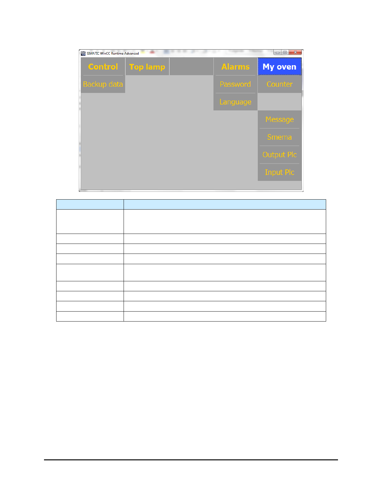
5.7.4 My Oven Menu
Name
Description
Backup Data
Opens a menu that lets you backup the PLC settings that are
necessary for proper operation of the UV-9 Cure Module. See 5.7.4.11
Backup Data/Factory Settings.
Password
Opens the Password Management screen. See 5.7.4.1 Password .
Language
Opens the Main screen. See 5.7.4.2 Language.
Counter
Opens the UV Lamp Counter screen. See 5.7.4.3 UV Lamp Counter.
PCB Dropped
Opens the Process Time Control screen. See 5.7.4.8 Process Time
Control.
Message
Opens the PLC Message screen. See 5.7.4.4 PLC Message.
SMEMA
Opens the SMEMA screen. See 5.7.4.5 SMEMA.
Output PLC
Opens the
Output PLC
screen. See 5.7.4.6 PLC Output.
Input PLC
Opens the Input PLC screen. See.5.7.4.7 PLC Input.
Figure 5-17 My Oven Menu
NOTE Figure 5-17 shows the standard menu. Depending on system configuration, there may be
additional buttons on the "My Oven" menu.
5-16 Operation