UV-9+Cure+Module+7269348_B+Manual.pdf - 第126页
Figure 9-1 Electrical Block Diagram 9-2 Block Diagrams
9 Block Diagrams
This section describes dispensing system electronic connections that may help in understanding cure
module operation and aid in troubleshooting.
9.1 Safety First
Use of engineering drawings to disassemble, service, and reassemble the UV-9 Cure Module promotes
good safety practices only when used in conjunction with the precautions in the Section 2 – Safety and
other sections of this manual.
CAUTION! Only trained service technicians should perform troubleshooting, servicing, and
parts replacement.
9.2 Electrical Block Diagram
The following electrical block diagram provides a basic outline of the electrical connections within the
UV-9 Cure Module.
Block Diagrams 9-1
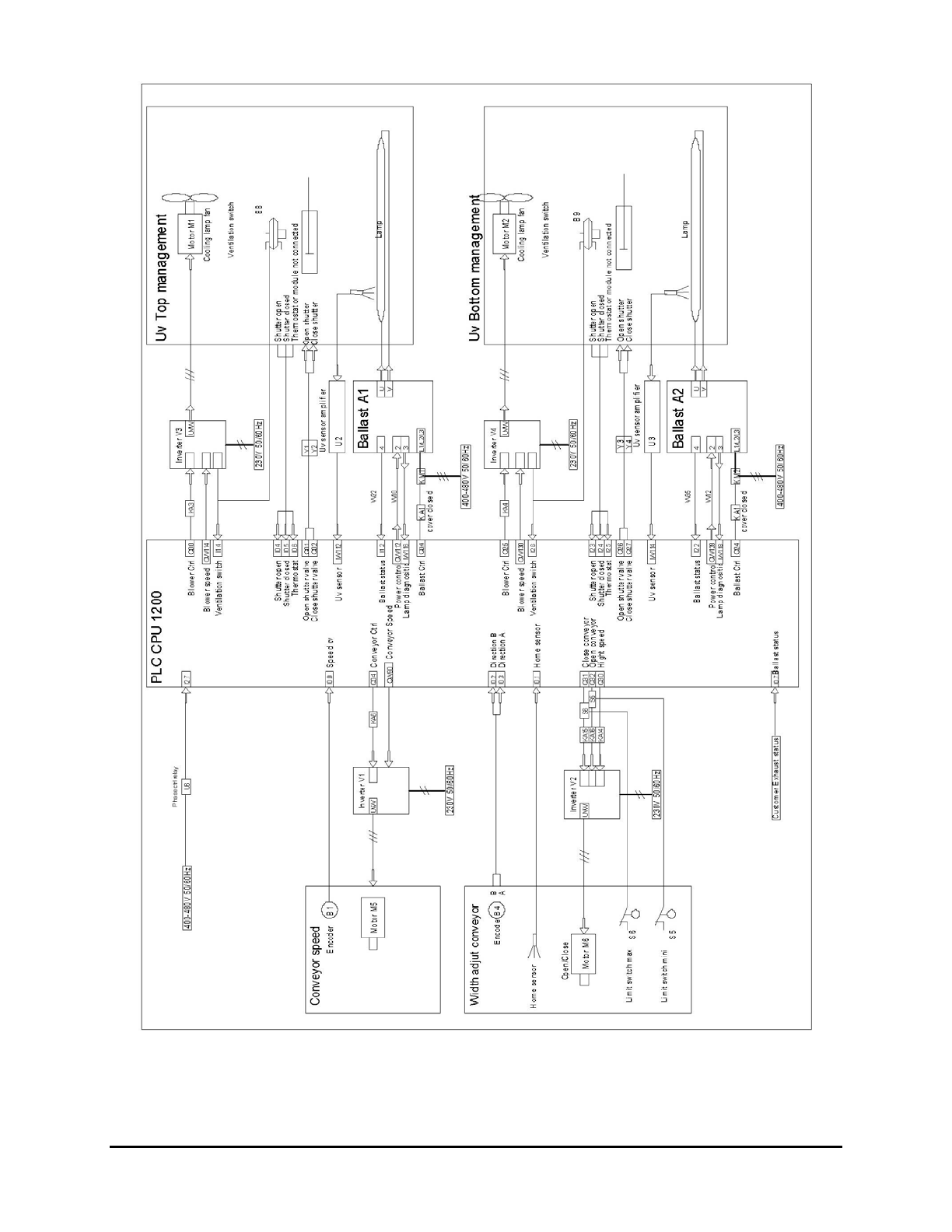
Figure 9-1 Electrical Block Diagram
9-2 Block Diagrams
10 Parts List
10.1 Overview
This section includes general information for ordering recommended spares and replacement parts for the
UV-9 Cure Module.
10.2 Safety First
Before attempting to replace any parts, please review the precautions in Section 2 – Safety.
CAUTION! Only trained service technicians should perform troubleshooting, servicing, and
parts replacement.
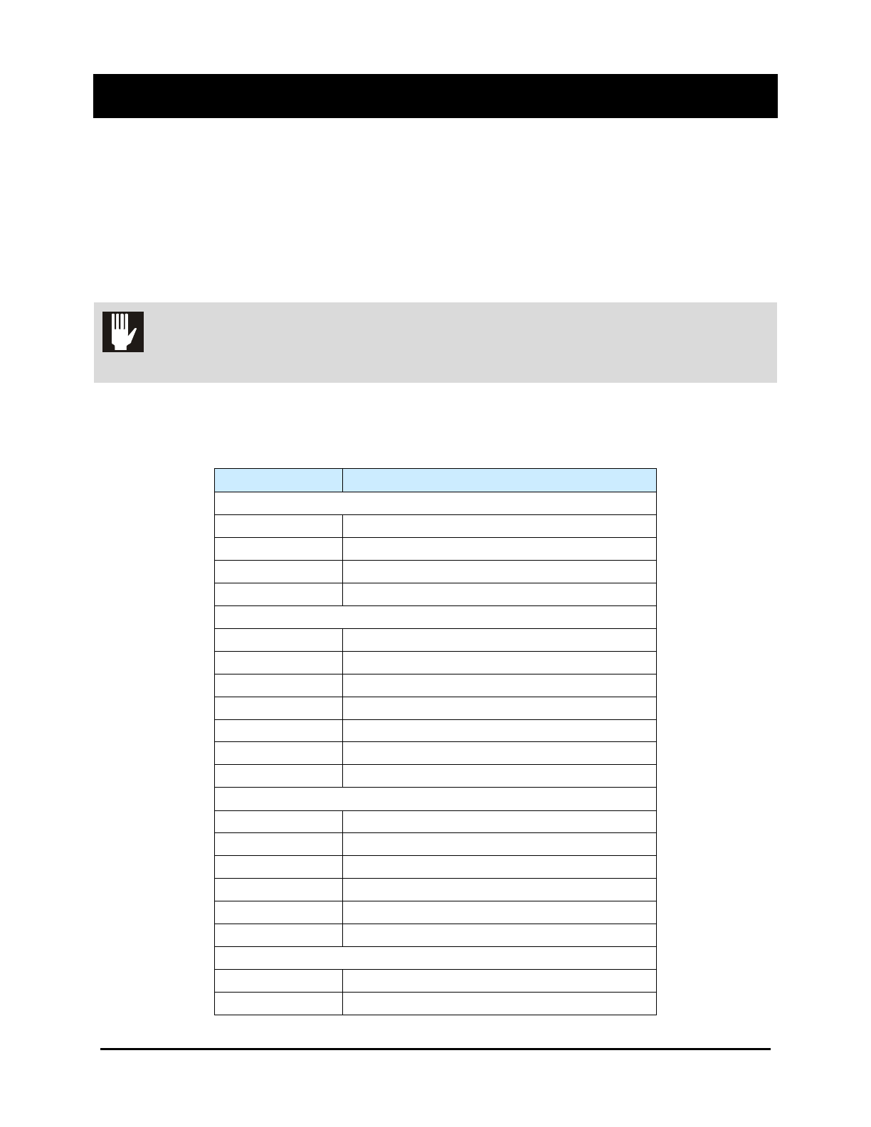
10.3 Spare Parts Kit
Table 10-1 Level 1 Spares
PART NUMBER DESCRIPTION
Lamps – choose as applicable
7252237 LAMP,UV,505MM,MERCURY
7252238 LAMP,UV,505MM,GALIUM
7252239 LAMP,UV,505MM,IRON
7252253 KIT,REFLECTOR,FOCUS,95MM UV-9
Conveyor
SPROCKET, CONV UV-9 - See exploded view
LINK, CHAIN - See exploded view
CHAIN, CONV. 5MM PIN - See exploded view
7263051 SPACER, SPROCKET CONV UV-9
7263042 COUPLING, TORQUE LIMITING
7252232 BELT,TOOTH,10x3000,T5
7252233 BELT,TOOTH,6x245,T2
Electronics
7252282 RELAY 1P 24VDC
7252283 RELAY 4P 24VDC
7252248 FAN,HELI,160-19
7252228 SENSOR, PRESSURE UV-9
7263050 SENSOR, EXIT UV-9
7252234 SENSOR,PHOTO,PROX,P4-130MM,NPN
Exhaust
7262775 HOSE Ø100MM,RED,REINFORCED
7262782 HOSE Ø125MM,RED,REINFORCED
Parts List 10-1