UV-9+Cure+Module+7269348_B+Manual.pdf - 第75页
5.7.2.3 Cl ose Loop Me nu ( Option ) Name Description Enable Button Activates the UV lamp. The background is yellow when the lamp is active. Disable Button Disables the UV lamp. Auto Button Enables the close loop option.…
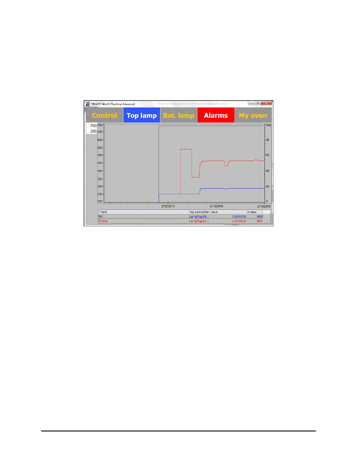
5.7.2.2 Graph
The graph is enabled with the closed loop option. The lamp graph displays a history of the following
parameters:
• Current output power in % (red curve)
• Measured irradiance in mW/cm² (blue curve)
It is a graphic tool that can be used for maintenance and process purposes.
Figure 5-13 Lamp Graph Screen (Top Lamp shown)
NOTE You can change the scale by selecting the value and entering a new one.
5-12 Operation
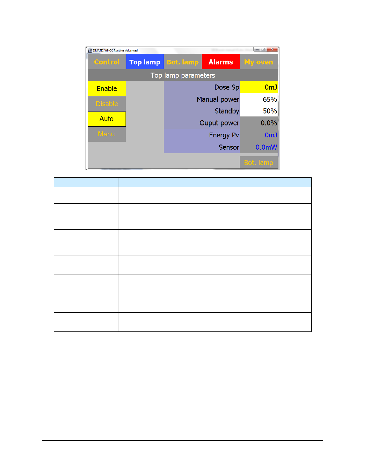
5.7.2.3 Close Loop Menu (Option)
Name Description
Enable Button
Activates the UV lamp. The background is yellow when the lamp is
active.
Disable Button
Disables the UV lamp.
Auto Button
Enables the close loop option. The back ground is yellow when the
close loop regulation is active.
Manu Button
Disables the close loop option and runs in open loop. The background
is yellow when the close loop regulation is active
Bot Lamp Button
Opens the Bottom Lamp Parameters tab.
Dose Sp
Set point in mj/cm² (closed loop option).
Select the field to change the setpoint.
Manual Power
Output power set point in % (open loop).
Select the field to change the setpoint.
Standby
Standby setpoint.
Output Power
Current output power (view only).
Energy Pv
Calculated current energy (view only).
Sensor
Measured irradiance in mw/cm² (closed loop option) (view only).
Figure 5-14 Lamp Parameters Screen - Close Loop Option Enabled (Top Lamp shown)
NOTE This menu allows you to edit the UV lamp parameters without using the recipe menu. To
save the values, you must go into the Recipe menu and save the recipe.
Refer to 6.5.5 Closed Loop Calibration Procedure for close loop calibration.
Operation 5-13
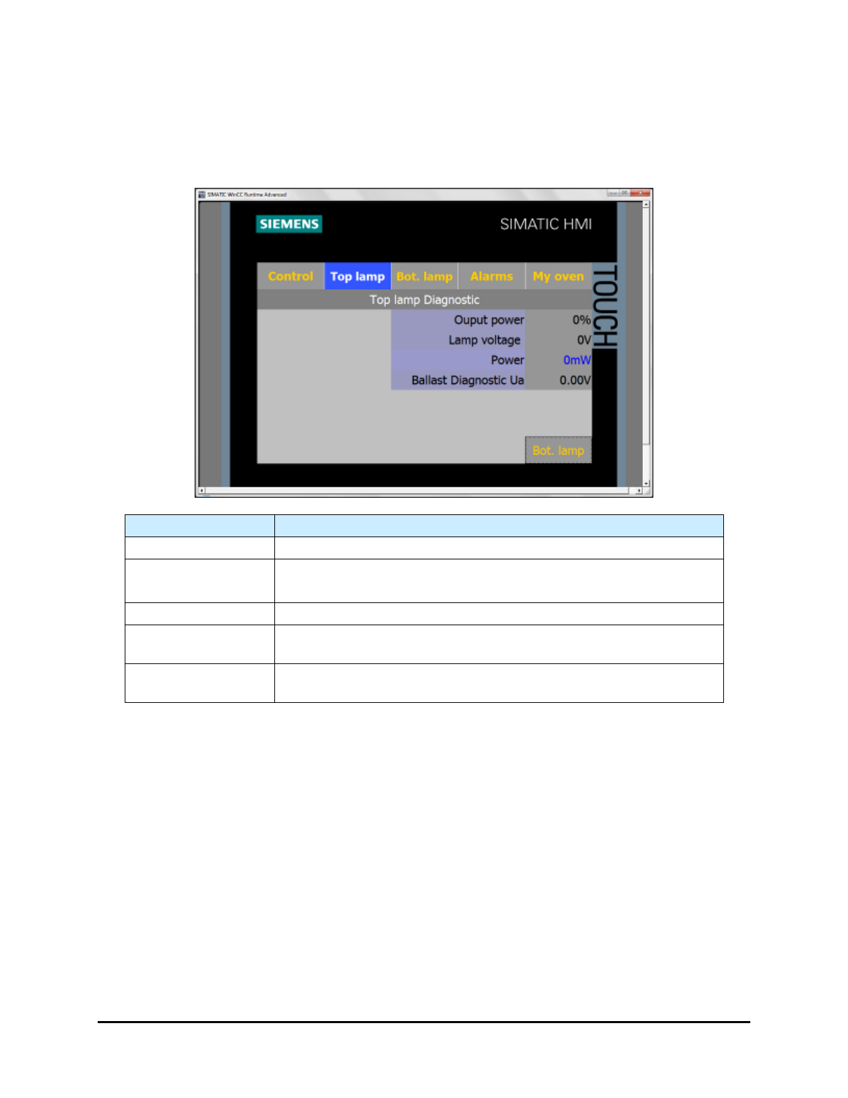
5.7.2.4 Diagnostic Screen
The Lamp Diagnostic screen (Figure 5-15) provides valuable information when troubleshooting the
system.
NOTE Only viewable in Maintenance and Admin Mode.
Name
Description
Output Power
Displays the current output power in % applied to the lamp.
Lamp Voltage
Displays the voltage applied to the UV lamp.
The background color is orange when the lamp is too cold (No UV).
Power
Displays the power in mw/cm² seen by the sensor (close loop).
Ballast Diagnostic
Ua
Displays the voltage (vdc) sent by the ballast to the PLC.
BotLamp / TopLamp
Button
Select BotLamp/TopLamp to toggle between the Bottom Lamp
Diagnostic screen and the Top Lamp Diagnostic screen.
Figure 5-15 Lamp Diagnostic Screen (Top Lamp shown)
5-14 Operation