UV-9+Cure+Module+7269348_B+Manual.pdf - 第61页
4.11 Top Lamp Height Adjustment The UV module has three height sett ings. Height is adjusted by mounti ng the alum inum profile s in a different hol e position at the side of the m odule. Changi ng lamp height will affec…
4.10.2 Oven with Close Loop Regulation (Option)
At start up of the oven or after a lamp replacement, the emitted radiation of the UV lamp must be checked
using a Power Puck or radiometer with a valid calibration certificate.
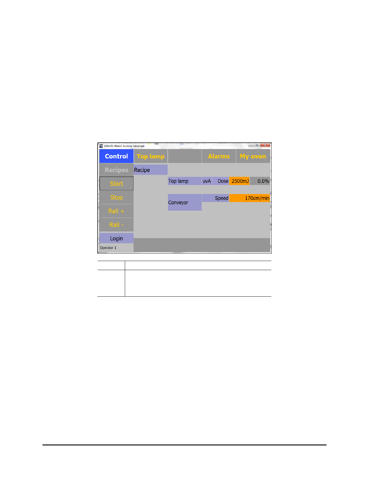
To adjust the UV lamp power:
1. From the technical specification sheet of the UV product, determine the conveyor speed and
the energy required for the UV product curing.
2. Enter the set point in mj/cm² and check with a Power Puck. If the difference is greater than
±5% between the measurement and the set point, a calibration of the close loop is required.
Perform the measurements with a cold radiometer. An internal temperature increase of
the UV power recorder corrupts the measurement.
Item
Description
1 Set Dose
2
Actual Delivered Power
3 Set Conveyor Speed
Figure 4-11 Setting the Output Power (Closed Loop)
3. Disable the Process Time Control option. See 5.7.4.8 Process Time Control.
4. Perform curing tests.
5. When the curing is correct, record the following parameters for future reference:
The output power of the lamps.
The values in mJ given by the Power Puck.
6. Re-enable the Process Time Control option. See 5.7.4.8 Process Time Control.
7. Every 120 hours, check and adjust the output power accordingly.
8. Replace the UV lamp when the output power reaches 100%.
NOTE The accuracy of a Power Puck is + /- 10%, typically + /- 5%.
4-10 Adjustments
4.11 Top Lamp Height Adjustment
The UV module has three height settings. Height is adjusted by mounting the aluminum profiles in a
different hole position at the side of the module. Changing lamp height will affect your irradiance and
dose. As you move the lamp out of focus, create more flooded UV to increase the dose. See Figure 4-13.
• 140 mm - lowest hole position, flood mode
• 110 mm - middle hole position, partially flood mode
• 75 mm - highest hole position, focus mode
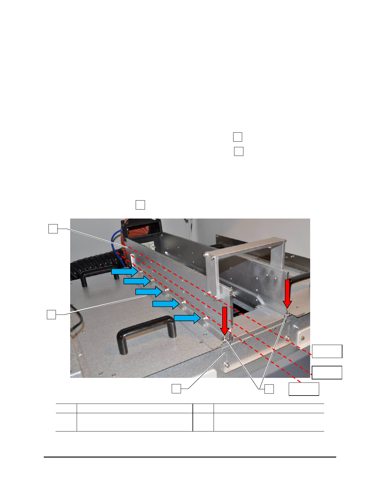
To adjust the top lamp height (Figure 4-12):
1. Remove the lamp box.
2. Remove the 2 screws on each end of the support beam (red arrows).
3. Remove the 5 screws on each side of the support beam (blue arrows).
4. Choose the new position and attach the support beam to that position with the screws
removed in Steps 2 and 3.
5. Fix the hole construction back on the tunnel.
6. Adjust the gap at front and back side of the module by loosening the screws and moving the
lid to close the cap .
Item
Description
Item
Description
1 Support Beam 3 Gap Plate (2 total – 1 on each end)
2
Side Screws (10 total – 5 on each side)
4
End screws (4 total – 2 on each end)
Figure 4-12 Adjusting the Lamp Height
3
4
2
1
2
3
4
110 mm
140 mm
75 mm
Adjustments 4-11
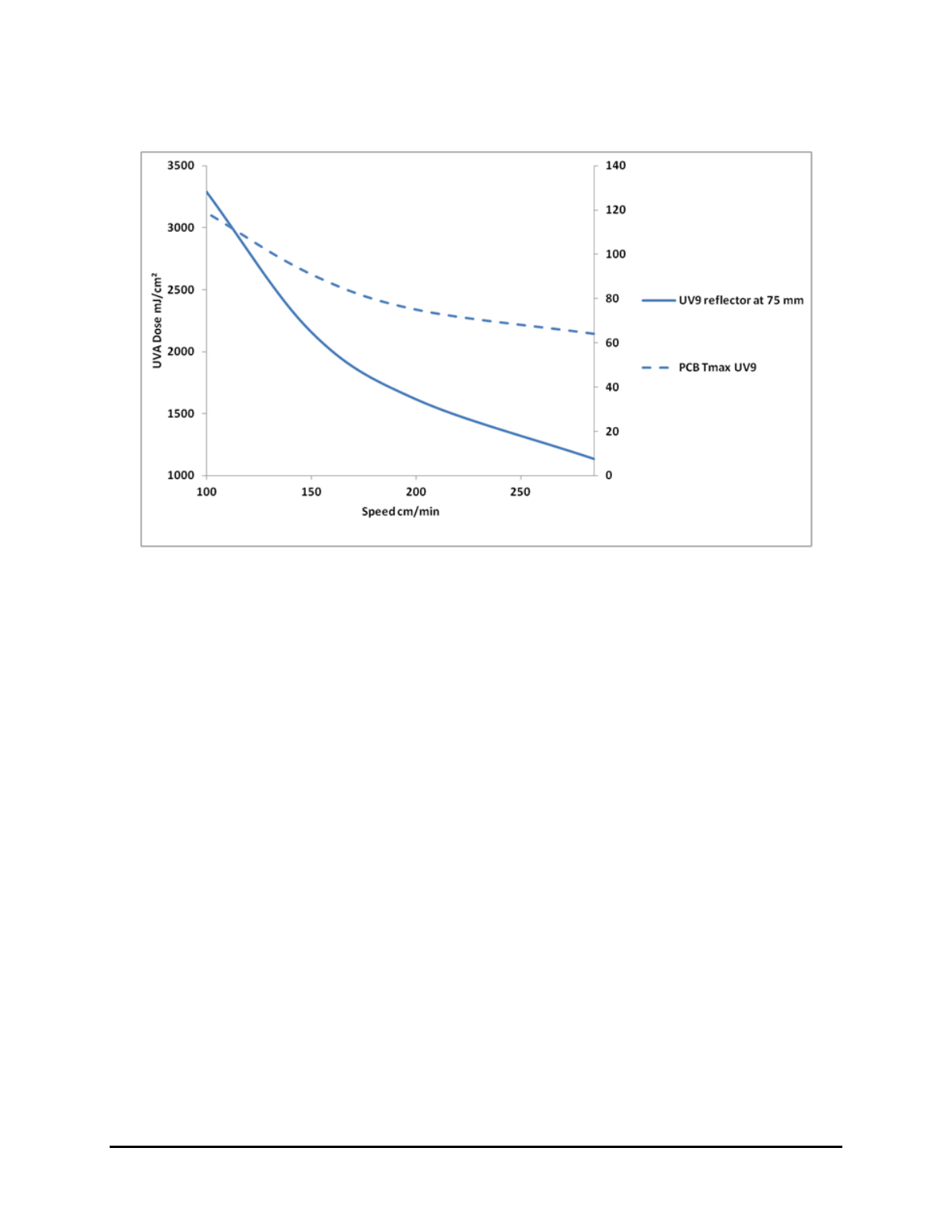
Figure 4-13 shows a performance graph at 75 mm height (Measured with EIT Power Puck 2).
Figure 4-13 75 mm Lamp Height Adjustment Performance Graph
4-12 Adjustments