UV-9+Cure+Module+7269348_B+Manual.pdf - 第117页
8 Technical Data 8.1 Overview This chapter pr ovides technical data for the UV -9 Cure Module. This data i s intended as a convenient referenc e for personne l planning system relocat ion, installa tion, or operation a n…
8 Technical Data
8.1 Overview
This chapter provides technical data for the UV-9 Cure Module. This data is intended as a convenient
reference for personnel planning system relocation, installation, or operation and others who may have an
interest in system performance characteristics. This chapter provides the following:
• Facility Requirements
• Declaration of Conformity
• System Specifications
• Seismic Safety
• Recommended Working Area Allowances
8.2 Safety First
Familiarity with the performance specifications and facility requirements in this section can provide
information leading to safe operation of the curing system. For additional safety information, see
Section 2 – Safety.
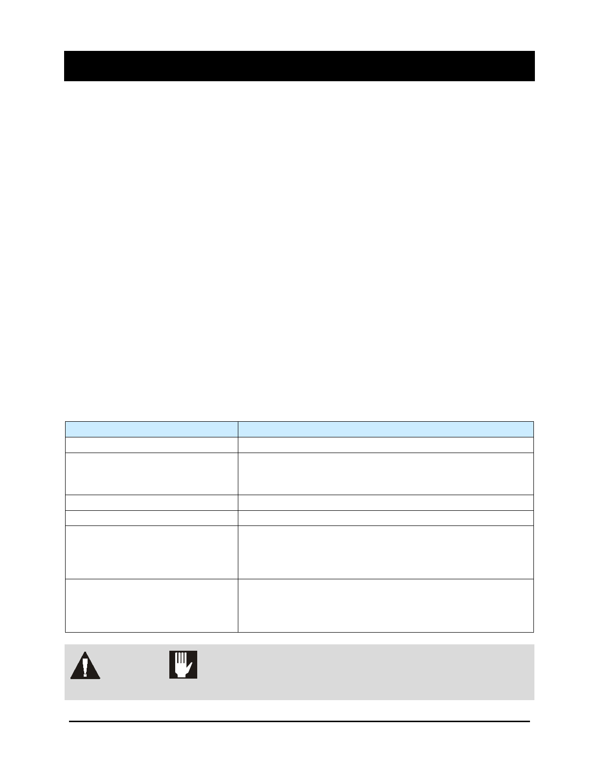
8.3 Facility Requirements
Table 8-1 lists the specifications and requirements for the system and applicable options which must be
supplied by the customer. Power cords are supplied by Nordson MARCH.
Table 8-1 Facility Requirements
Item
Requirement
Power 400VAC 3 phase
Power Rating
Top Lamp
Top and Bottom Lamps
7 kW
14 kW
Mode N+EARTH, TT or TN
Main Power Supply 100/120/220/240 VAC, 50/60 Hz, 10 A
Ventilation Air Exhaust
550 m
3
/h (top lamp)
1100 m
3
/h (top and bottom lamps)
(382.5 SCFM @ 1.57 in. WC, 10 in. exhaust duct)
See 3.11 Connecting the Exhaust for more information.
Pneumatic Connection (optional)
(For systems equipped with entrance
and/or exit shutters)
Air Pressure: 600 kPa (87 psi)
Connecting Pipe: 6 mm
Consumption: < 0.02 m
3
/H
See 3.12 Pneumatic Connection (Shutter Option).
WARNING! CAUTION!
The UV-9 Cure Module is not compatible with Neutral IT.
Technical Data 8-1
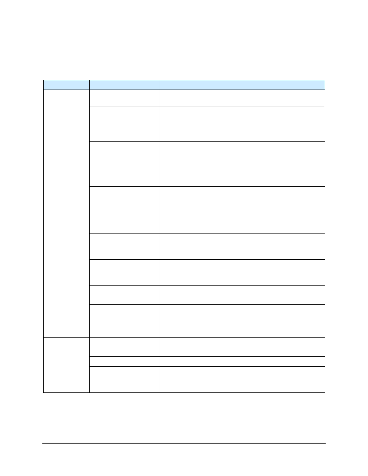
8.4 System Specifications
The UV-9 Cure Module is designed for indoor use only. Table 8-2 lists the specifications for the overall
UV-9 Cure Module and its major components.
Table 8-2 System Specifications
Item
Characteristic
Specification
Overall
System
Enclosure
Powder-coated aluminum completely houses the process
chamber, electronics, pump and generator
Footprint
2000 W x 2086 H x 1200 D (mm)
27.44 W x 59.56 H x 44.4 D (in.)
Width w/o conveyor extensions: 1400 mm
Height w/o monitor and light beacon: 1526 mm
Component Clearance
100 mm above and below board
Weight
250 kg (551 lbs)
w/ conveyor extensions: 280 kg (617 lbs)
Short Circuit Current
Rating (SCCR)
6 kA
IEC Installation
Category
(Over-voltage)
Installation category II: Local level, appliances, portable
equipment, etc., with smaller transient over-voltages than
distribution level and fixed equipment.
IEC Pollution Degree
Pollution Degree 2: Normally only non-conductive pollution
occurs. Occasionally, however, a temporary conductivity
caused by condensation must be expected.
Maximum Operating
Altitude:
6564 feet (2000 meters)
Temperature Range: 21 °F to 56 °F (12 °C to 30 °C)
Maximum Relative
Humidity:
80 percent at 56 °F (31 °C), decreasing linearly to 50
percent at 21 °F (12 °C).
Sound Pressure < 72dB(A)
Recommended
Working Allowances
In Front: 914 mm (36 in)
In Back: 914 mm (36 in)
Configuration
Designed to be configured in-line. SMEMA 1.2 compatible
for standard integration with upstream and downstream
systems and/or freestanding loaders.
Compliance CE compliant.
Conveyor
Acceptable Board
Width
Standard Conveyor: 50 to 420 mm (2.0 to 16.5 in.)
Heavy Duty Conveyor: 50 to 400 mm (2.0 to 15.7 in.)
Height from Floor 920 to 1000 mm (36.22 to 39.37 in.)
Chain Speed 300 to 1500 mm / min (1 – 4.92ft / min)
Flow
Left to right (standard)
Right to left (optional)
8-2 Technical Data