UV-9+Cure+Module+7269348_B+Manual.pdf - 第62页
Figure 4- 13 shows a p erformance gra ph at 75 mm height (Meas ur ed with EIT Power Puck 2) . Figure 4- 13 75 mm Lam p Height Adjustment Perf ormance Graph 4-12 Adjustments
4.11 Top Lamp Height Adjustment
The UV module has three height settings. Height is adjusted by mounting the aluminum profiles in a
different hole position at the side of the module. Changing lamp height will affect your irradiance and
dose. As you move the lamp out of focus, create more flooded UV to increase the dose. See Figure 4-13.
• 140 mm - lowest hole position, flood mode
• 110 mm - middle hole position, partially flood mode
• 75 mm - highest hole position, focus mode
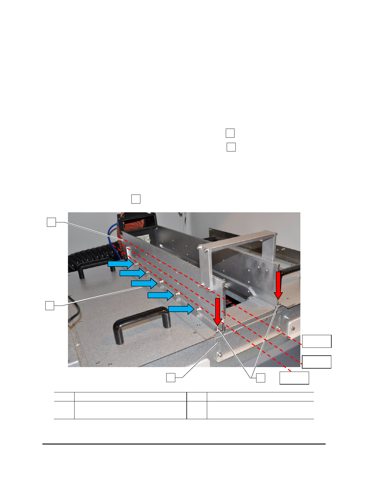
To adjust the top lamp height (Figure 4-12):
1. Remove the lamp box.
2. Remove the 2 screws on each end of the support beam (red arrows).
3. Remove the 5 screws on each side of the support beam (blue arrows).
4. Choose the new position and attach the support beam to that position with the screws
removed in Steps 2 and 3.
5. Fix the hole construction back on the tunnel.
6. Adjust the gap at front and back side of the module by loosening the screws and moving the
lid to close the cap .
Item
Description
Item
Description
1 Support Beam 3 Gap Plate (2 total – 1 on each end)
2
Side Screws (10 total – 5 on each side)
4
End screws (4 total – 2 on each end)
Figure 4-12 Adjusting the Lamp Height
3
4
2
1
2
3
4
110 mm
140 mm
75 mm
Adjustments 4-11
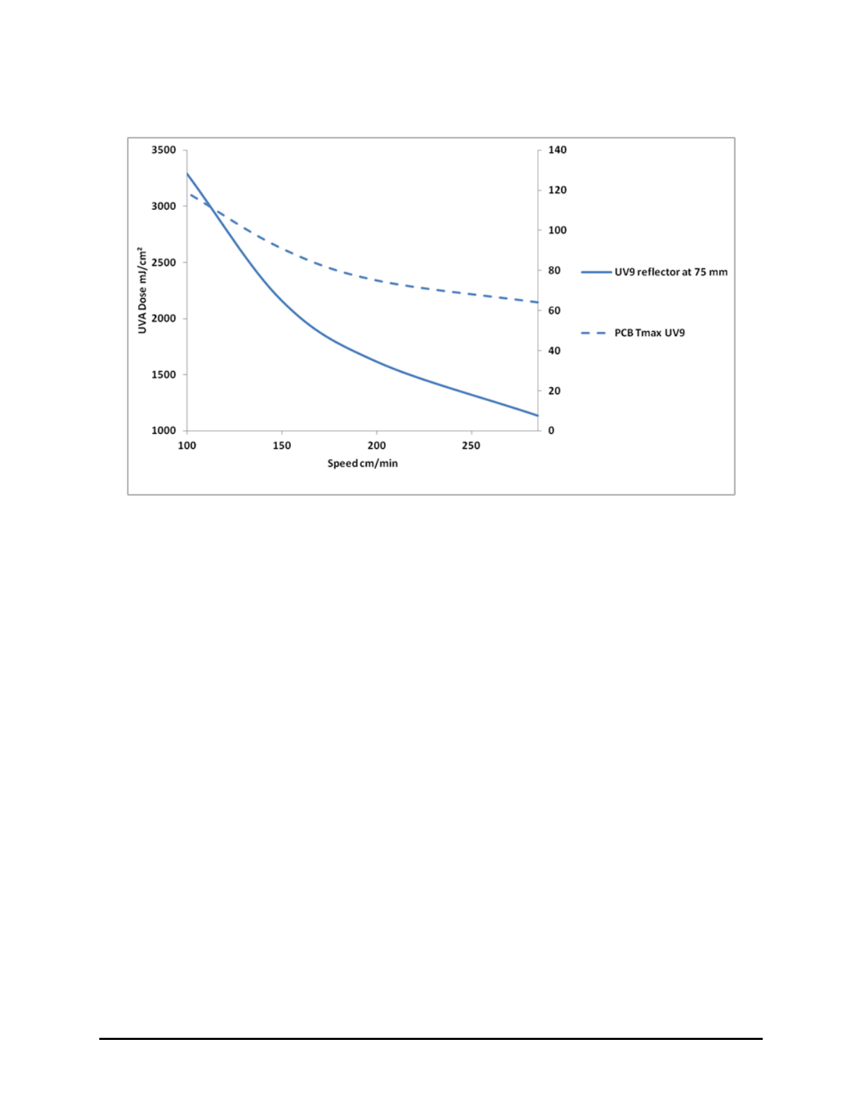
Figure 4-13 shows a performance graph at 75 mm height (Measured with EIT Power Puck 2).
Figure 4-13 75 mm Lamp Height Adjustment Performance Graph
4-12 Adjustments

5 Operation
5.1 Overview
Before operating your UV-9 Cure Module, it may be helpful to familiarize yourself with the basics of
how the system works. This section covers the following topics:
• Theory of Operation
• System Startup
• Running Production
• Software Description
• System Shutdown
NOTE In this section, typical UV-9 Cure Module configurations are considered. However,
operational details may vary with the configuration of your system.
5.2 Safety First
Before operating the UV-9 Cure Module, please review the information presented in Section 2 – Safety.
5.3 Theory of Operation
The heart of the UV-9 Cure Module is in the arc lamp technology with adjustable UV intensity combined
with a unique ventilation design that dissipates heat generated from the UV lamp. This combination keeps
the temperature and rate of rise at acceptable levels while maximizing production and lamp lifetime as the
lamps run cooler.
A closed loop feature insures process reliability and compensates for the eventual lamp degradation by
measuring and adjusting power levels for Ultraviolet A (UVA) radiation. Therefore, the desired profile is
maintained within +/- 5% of the programmed specifications. Other options and lamp types are also
available to further insure the oven meets customer specific needs while maintaining high performance.
Additionally a standard SMEMA-compatible chain conveyor with 5 mm pins enables the processing of
boards and is easily integrated with any dispensing system. The conveyor can be configured for either
left-to-right or right-to-left flow with electrical width adjustment.
UV-9 Cure Module electronics typically perform the following functions:
• Coordinate conveyor motion with upstream machines
• Control conveyor speed and UV lamp operation
• Sense workpiece progress through the UV-9 Cure Module
• Move the dispensed workpiece toward the downstream end of the conveyor
• Coordinate the motions of the conveyor with downstream machines
Operation 5-1