UV-9+Cure+Module+7269348_B+Manual.pdf - 第110页
6-16 Maintenance 6.6 UV Module Quartz Glass Replacement 6.6.1 Upper UV Module (UV-9 Version 1 Only) To replace the UV module quartz glass: 1. Check that the Main Power Switch is in the ON position and locked. 2. Disconne…
7. Perform a UV measurement and enter the UVA results; intensity (mW/cm²) and dose
(mJ/cm²) in the High Power Value and UVA fields.
Calibration at 100% power is now complete.
8. Set
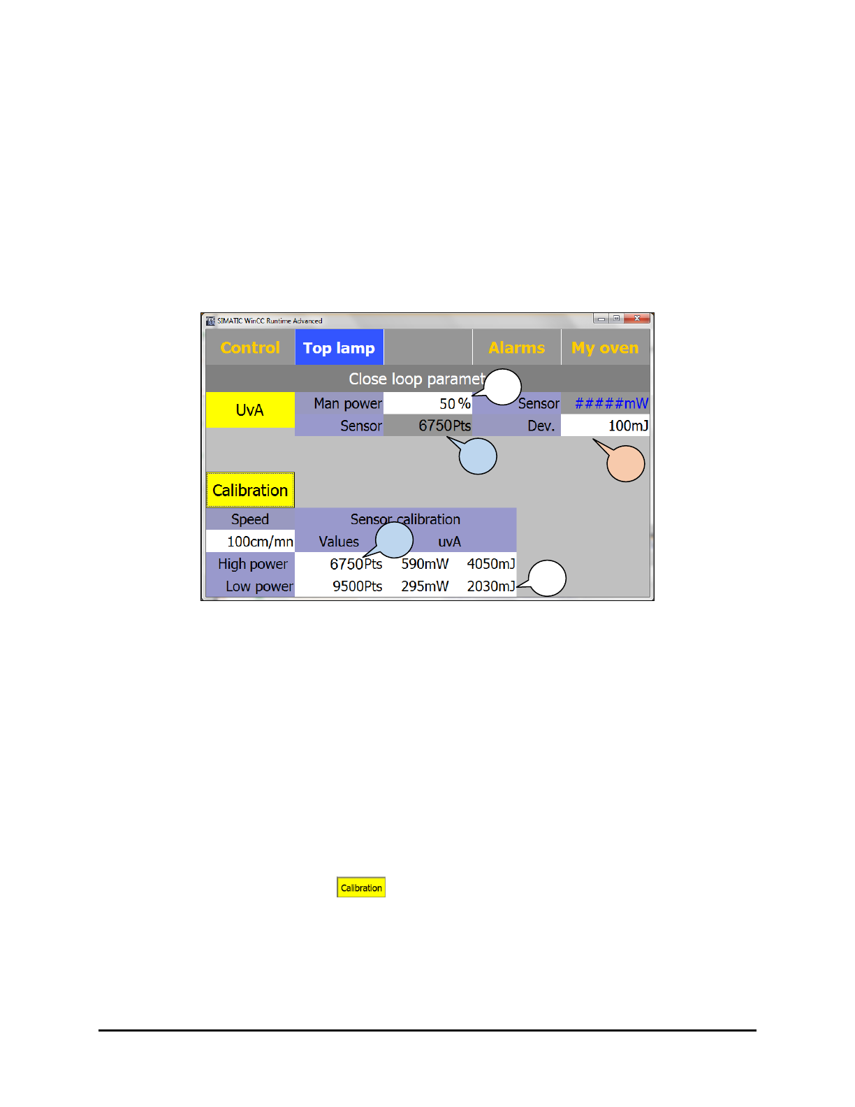
Man Power to 50% (Figure 6-18).
This control box is an active control box; it sets the value.
Wait 15 minutes for temperature stabilization before calibrating.
9. Copy the Sensor read value in the Sensor Calibration Low Power input textbox.
The UV sensor resolution varies per machine as they are individually validated. The
read value in terms of points represents the analog input value at the PLC.
Figure 6-18 Closed Loop Parameters Screen – Low Power
10. Position the UV puck on a flat carrier or surface and point the puck sensor toward the lamp
top or bottom.
Make sure the puck is at the same height as the substrate to get an accurate UV
measurement.
11. Perform a UV measurement and enter the UVA results; intensity (mW/cm²) and dose
(mJ/cm²) in the Low Power field.
Calibration at 50% power is now complete.
12. Set the
Dev (deviation or tolerance) on the UV sensor reading. The standard value is
100 mJ, which means that the UV-9 is giving the UV process free as soon 100 mJ
variation is measured from the set point.
13. When finished, click on
again to activate the SMEMA signals (the background
should be gray instead of yellow).
14. Use the UV puck to validate the calibration by comparing the measured dose and intensity
values with the UV-9 values on the Top/Bottom Lamp Parameters screen.
12
8
9
9
11
Maintenance 6-15
6-16 Maintenance
6.6 UV Module Quartz Glass Replacement
6.6.1 Upper UV Module (UV-9 Version 1 Only)
To replace the UV module quartz glass:
1. Check that the Main Power Switch is in the ON position and locked.
2. Disconnect the power plug located at the rear of the UV assembly.
3. Turn the front key.
4. Pull out and remove the UV assembly.
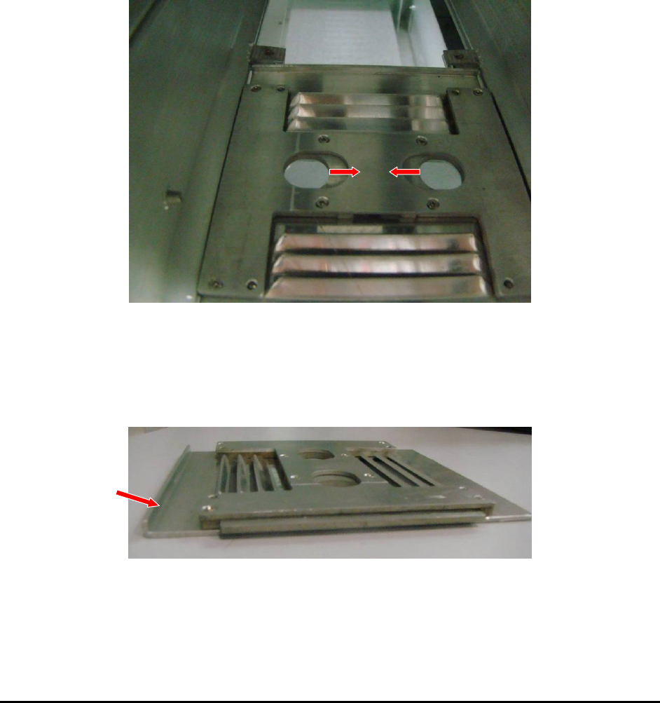
5. Remove the terminal cover by pressing on the 2 tabs towards the center (Figure 6-19).
Figure 6-19 Terminal Cover Tabs
6. Slide the quartz glasses through the supports.
7. Reinstall the terminal cover. Take care that the vertical fold is on the quartz glass side
(Figure 6-20).
Figure 6-20 Terminal Cover Vertical Fold
6.6.2 Lower UV Module (Double-Sided Option Only)
To install the quartz glass in the lower module:
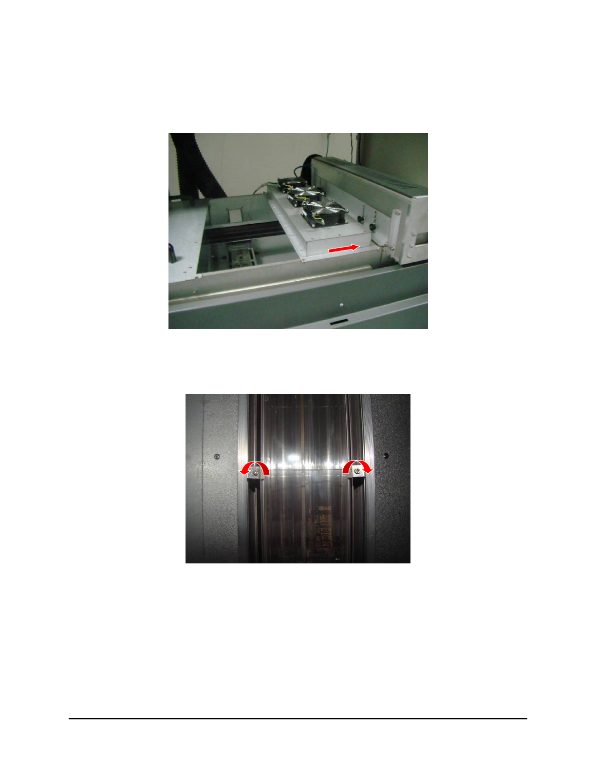
1. Remove the cover next to the upper UV Lamp module and slide the cooling module
towards the upper UV module (Figure 6-21).
Figure 6-21 Accessing the Lower UV Module
2. Loosen the screws in the quartz glass support brackets (one on each side of the UV module)
without removing them and turn the upper brackets 180° (Figure 6-22).
Figure 6-22 Quartz Glass Support Brackets
3. Slide the quartz glass into the supports.
4. Turn the upper brackets 180° and tighten them down over the quarts glass.
5. Slide the cooling module over the UV module and replace the adjacent cover.
Maintenance 6-17