UV-9+Cure+Module+7269348_B+Manual.pdf - 第39页
7. Raise or lower each lev eler (foot) as fol lows until they all touch the floor: a. Loosen the 1½ - i nch lock nut on the le veler. See Figure 3-2. b. Adjust the 1½ - inch post n ut to raise or lo wer each leveler as r…
3.5 Unpacking and Placing the UV-9 Cure Module
CAUTION! Installation procedures should only be performed by trained service technicians.
To unpack and place the UV-9 Cure Module:
1. If the UV-9 Cure Module was shipped in a wooden crate, use a flat bar and hammer to
remove the lid and sides of the crate.
WARNING! CAUTION!
Personnel should wear gloves and safety glasses while removing the top and sides
of the crate. Sufficient personnel should be used to lift and control the crate to
prevent serious injury to personnel or damage to the curing module. See 2.4 Basic
Safety Precautions and Practices for details.
2. Remove all packaging material from the outside and inside of the UV-9 Cure Module.
3. Remove any bolts and brackets securing the UV-9 Cure Module to the pallet.
4. Use a forklift to gently lift the UV-9 Cure Module off of the pallet.
NOTE Lift the UV-9 Cure Module from the very bottom, between the feet.
5. Place the UV-9 Cure Module over the selected location where it will be operated, but DO
NOT completely lower the forklift at this time.
NOTE Leave a 10 mm free space between the oven and the upstream and downstream
conveyors.
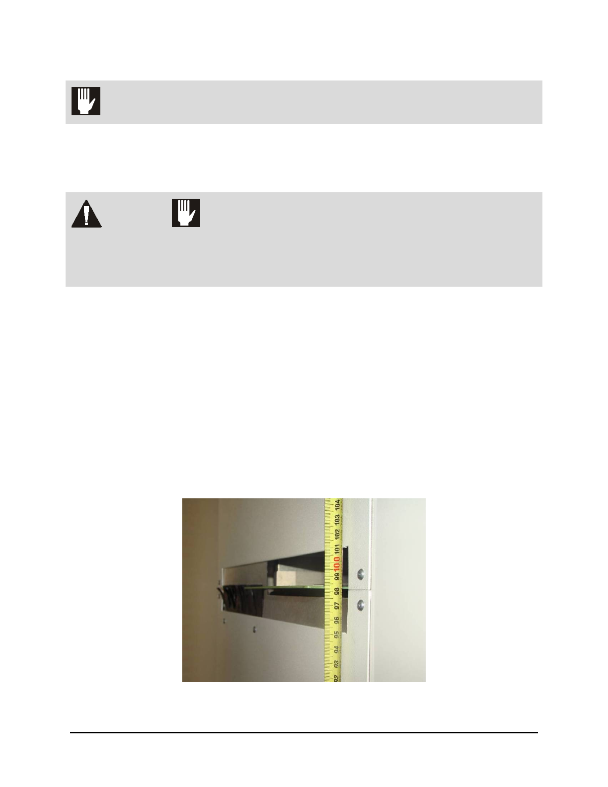
6. Adjust the forklift height until the UV-9 Cure Module is approximately at the height
required to mate with upstream and downstream systems.
Figure 3-1 Height Adjustment
3-2 Installation
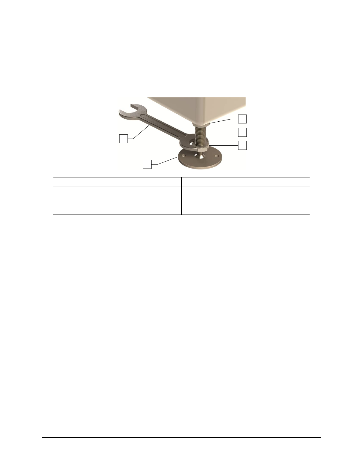
7. Raise or lower each leveler (foot) as follows until they all touch the floor:
a. Loosen the 1½-inch lock nut on the leveler. See Figure 3-2.
b. Adjust the 1½-inch post nut to raise or lower each leveler as required.
Turning the post nut clockwise raises the leveler. Turning the post nut
counterclockwise lowers the leveler.
c. Tighten the lock nut finger tight.
Item
Description
Item
Description
1 Lock Nut 4 Leveler (foot)
2 Post 5 1 1/2-inch Wrench
3 Post Nut
Figure 3-2 Adjusting the Levelers
3.6 Unpacking the Accessories
The accessories received will vary depending upon the configuration of your UV-9 Cure Module. These
accessories may include UV lamps, power supplies, power cords, tool and maintenance kits, and
equipment manuals. They may be in a crate, plastic wrapped on a skid, or secured on the cure module.
Tools and Materials Needed:
• Flat Bar
• Appropriate Personal Protective Equipment
• Pen or Pencil
To unpack the accessories:
1. Locate the shipping list and place it in a safe location.
2. If the accessories were shipped in a wooden crate, use the flat bar and hammer to remove
the crate lid.
3. As you uncrate or unwrap each item, identify it, and place a check mark next to the item
name on the shipping list.
If any parts or accessories are missing, please contact Nordson ASYMTEK Technical
Support.
1
5
4
3
2
Installation 3-3
3.7 Leveling the UV-9 Cure Module
CAUTION! This procedure should only be performed by a trained service technician.
Tools and Materials Needed:
• Adjustable Wrench
• Level
To level the oven in the production line:
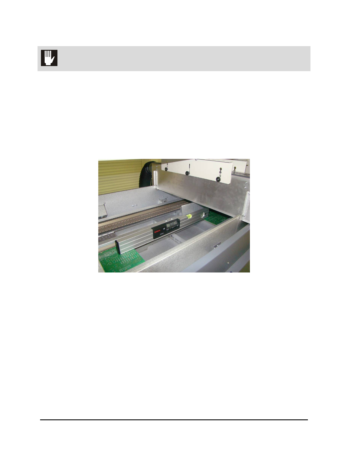
1. Open the hood and place the level in the center of the front conveyor rail, along the length
of the rail (Figure 3-3).
2. Remove the tunnel modules for access to the conveyors.
Figure 3-3 System Leveling – Left to Right
3. Observe the position of the bubble within the level’s window. The bubble should be
centered indicating the UV-9 Cure Module is level from side-to-side.
4. If necessary, adjust the levelers (feet) as follows:
a. Loosen the 1½-inch lock nut on the leveler. See Figure 3-2.
b. Adjust the 1½-inch post nut to raise or lower each leveler direction until the level’s
bubble is centered, indicating that the system is level from side-to-side.
Turning the post nut clockwise raises the system. Turning the post nut
counterclockwise lowers the system.
c. Tighten the lock nut finger tight.
5. Place the level at the conveyor entrance, with one end of the level on the front rail and the
other end on the back rail (Figure 3-4).
3-4 Installation