UV-9+Cure+Module+7269348_B+Manual.pdf - 第57页
4.8 Internal UV Radiation Traps Adj ustment The UV - 9 Cure Module tunnel is equippe d with light traps to reduce the light reflections inside the tunnel. They are locat ed as follows : • Light traps unde r UV module • L…
4.7 Internal UV Radiation Shutters Height Adjustment
The height of the radiation trap shutter can be adjusted to accommodate the height of components on the
underside of the board.
To set the height of radiation trap shutter:
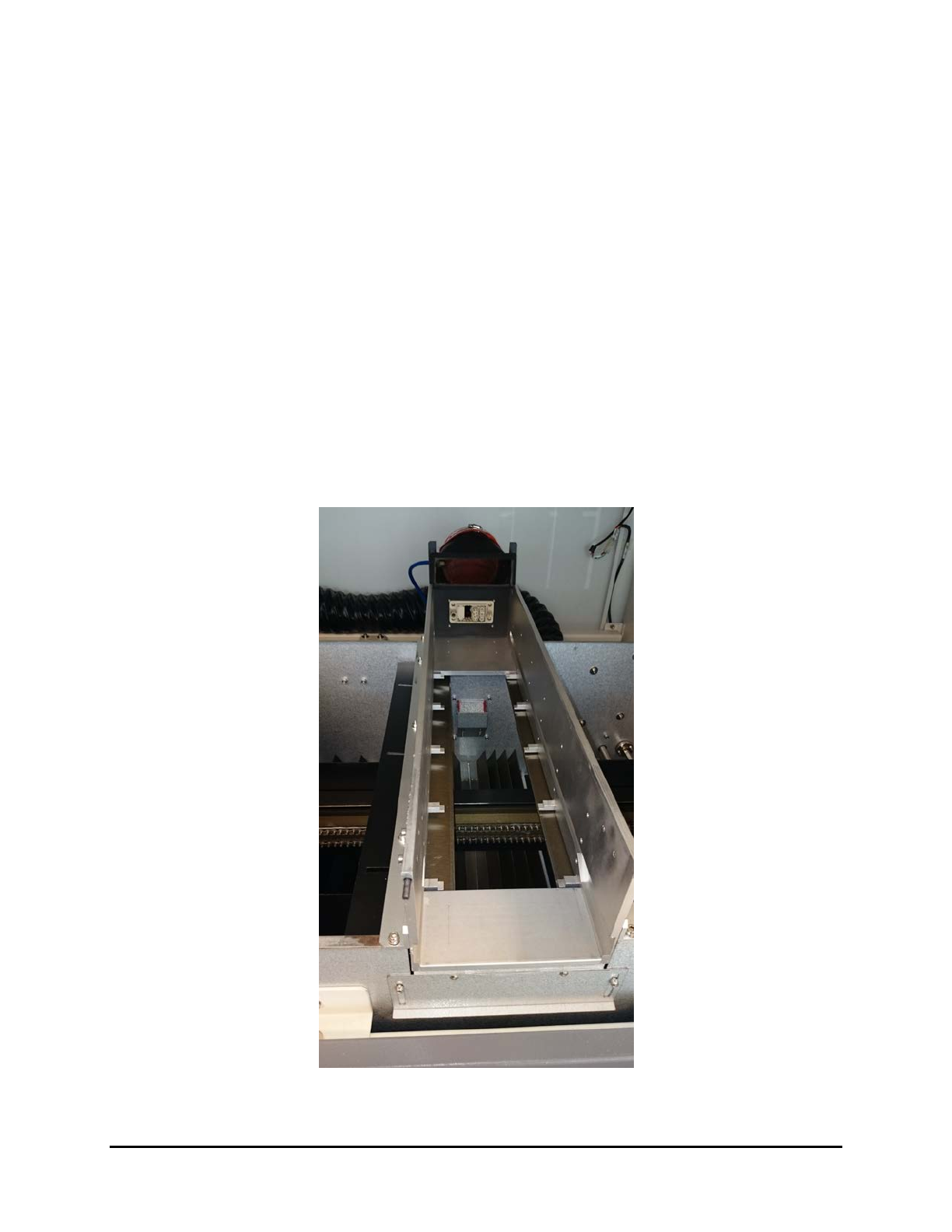
1. Open the hood and remove the two UV radiation traps from the tunnel.
There are four shutters, two at the entrance and two at the exit of the oven (Figure 4-7).
Figure 4-7 UV Radiation Trap Shutters
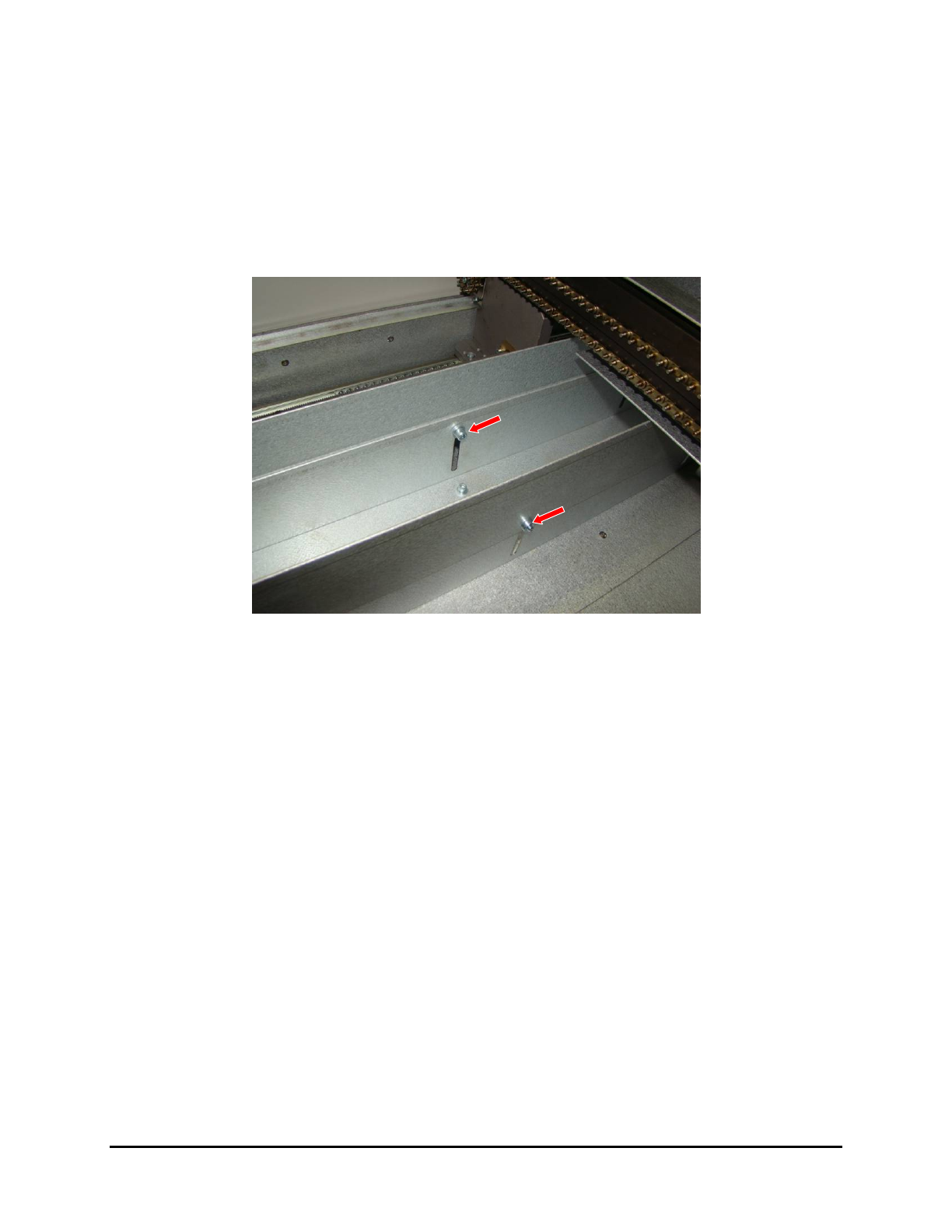
2. Loosen the two screws on each shutter and slide the shutters up or down to the correct
height and retighten the screws.
4-6 Adjustments
4.8 Internal UV Radiation Traps Adjustment
The UV-9 Cure Module tunnel is equipped with light traps to reduce the light reflections inside the
tunnel.
They are located as follows:
• Light traps under UV module
• Light traps under tunnel
• Light traps conveyor shields
• UV module light traps
The light traps on the top module are the only adjustable light traps (Figure 4-8). They can be adjusted
horizontally or vertically to reduce the low irradiance beams on the substrate (<15 mW). These low
irradiance beams can have a direct impact on the process and the quality of the curing (physical aspect of
the coating). Blocking the low irradiance beam reduces the difference in the behavior between the true
cure and the surface cure.
NOTE Changing the setting of the light traps, may have an impact on the closed loop calibration
(does not impact the high point of irradiance, but the total dose).
Figure 4-8 Light Traps – UV Module
Adjustments 4-7
4.9 External UV Shutters Adjustment
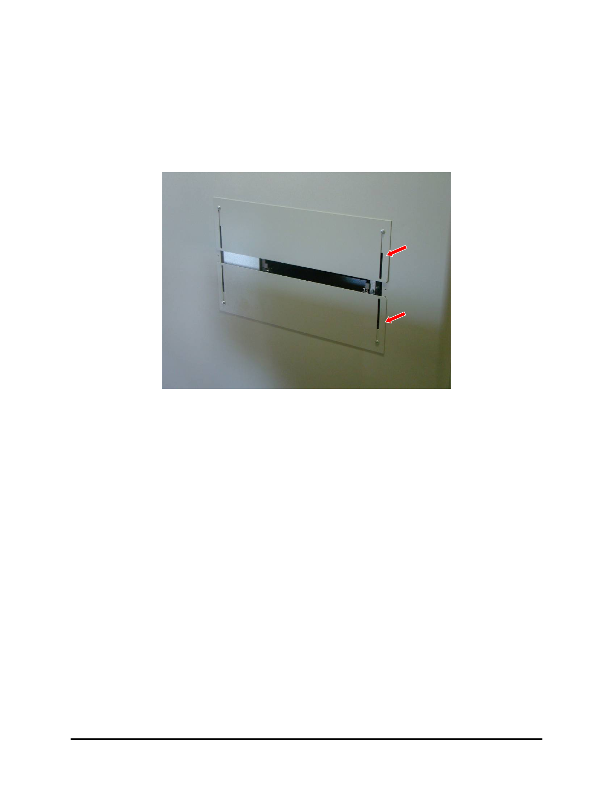
The openings at the entrance and exit of the UV-9 Cure Module can be adjusted to accommodate the
thicknesses of the boards being cured.
To adjust the external UV shutters:
1. Loosen the screws and slide the shutters up or down according to the component’s height
(Figure 4-9).
Figure 4-9 External UV Shutters
2. Tighten the screws after adjustment.
NOTE A sliding shutter automatically closes off the free space to the rear of the adjustable
conveyor rail.
4-8 Adjustments