UV-9+Cure+Module+7269348_B+Manual.pdf - 第87页
5.7.4.8 Process Ti me Control Screen (Option) If the Process Time Control option is installed, sele ct the Process Time Control button on the "My Oven" me nu to open this scr een. NOTE A yellow background i n…
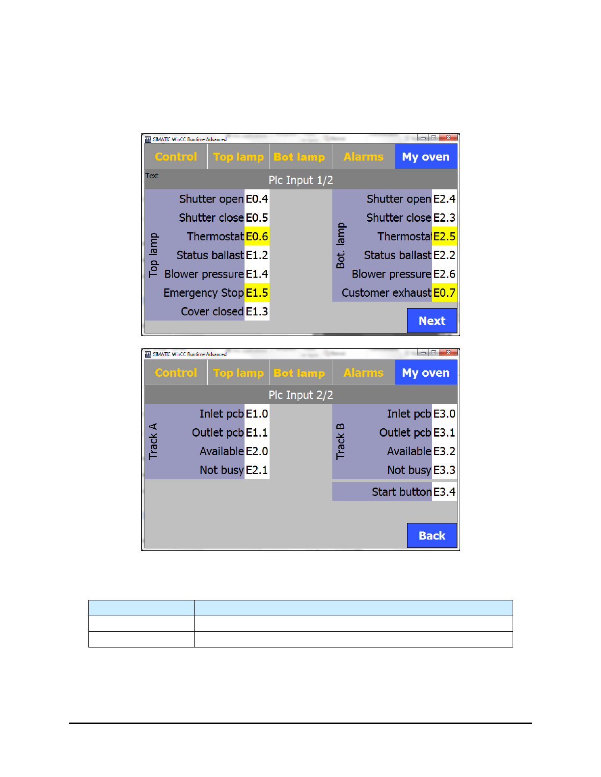
5.7.4.7 PLC Input Screens
The PLC Input screens display the active/inactive status of the inputs. Select the Input PLC button on the
"My Oven" menu to open this screen.
NOTE The background of the inputs is yellow when they are active.
Figure 5-24 PLC Input Screens
Table 5-1 PLC Input Screen Controls and Indicators
Name
Description
Next
Proceeds to Page 2 of the PLC Input screen.
Back
Returns to Page 1 of the PLC Input screen.
5-24 Operation
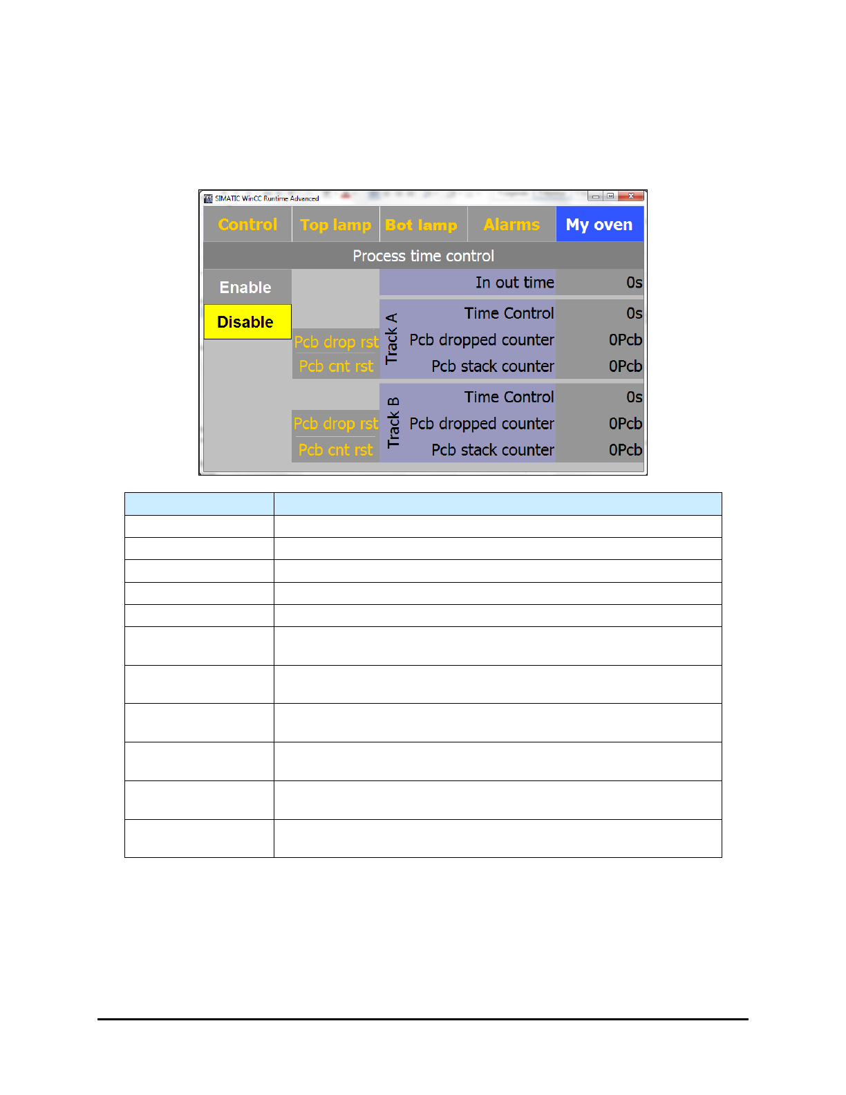
5.7.4.8 Process Time Control Screen (Option)
If the Process Time Control option is installed, select the Process Time Control button on the "My
Oven" menu to open this screen.
NOTE A yellow background indicates the function is active.
Name Description
Enable
Enables the time control.
Disable
Disables the time control.
Pcb drop rst
Resets the dropped board counter for the applicable track to zero (0).
PCB cnt rest
Resets the stack counter for the applicable track to zero (0).
In Out Time (s)
Displays the calculated travel time (in accordance with the speed).
Track A – Time
Control
Displays the travel time of the next board going out on Track A.
Track A – PCB
Dropped Counter
Displays the number of dropped boards on Track A.
Track A – PCB
Stack Counter
Displays the number of boards on Track A in the oven.
Track B – Time
Control
Displays the travel time of the next board going out on Track B.
Track B – PCB
Dropped Counter
Displays the number of dropped boards on Track B.
Track B – PCB
Stack Counter
Displays the number of boards on Track B in the oven.
Figure 5-25 Process Time Control Screen
NOTE When performing tests, Process Time Control should be disabled.
Operation 5-25
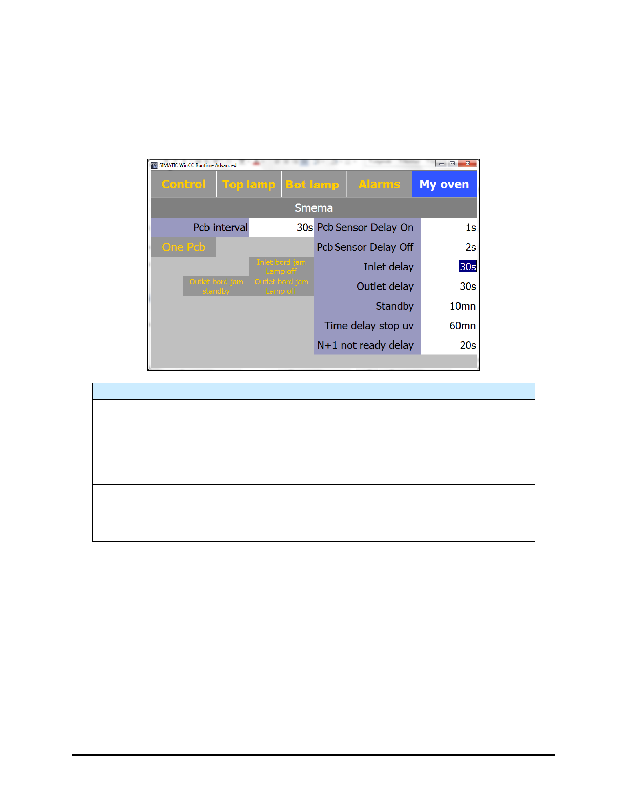
5.7.4.9 Board Jam Detection Screen (Option)
This option detects a board jam at the entrance or exit of the UV-9 Cure Module. The alarms
sounds if the entrance and/or exit sensor detects a board after the PCB Sensor Delay On
(entrance) or PCB Sensor Delay Off (exit) time has expired.
NOTE The background is yellow when a function is active.
Name
Description
Inlet Delay
The maximum time (in seconds) that the board is at the entrance
sensor before the “Jam” alarm sounds.
Outlet Delay
The maximum time (in seconds) that the board is at the exit sensor
before the “Jam” alarm sounds.
Inlet Board Jam
Lamp Off
If you activate this feature, the UV-9 lamp turns off if there is a board
jam at the entrance.
Outlet Board Jam
Standby
If you activate this feature, the UV-9 Cure Module will go into standby
mode if there is a board jam at the exit.
Outlet Board Jam
Lamp Off
If you activate this feature, the UV-9 lamp turns off if there is a board
jam at the exit.
Figure 5-26 SMEMA - Board Jam Detection
NOTE If the oven turns off, there is a 180 second cooling time before the oven can be turned
on again.
5-26 Operation