UV-9+Cure+Module+7269348_B+Manual.pdf - 第42页
3.8 Connecting the Power CAUTION! This proce dure should only be per formed by a trai ned service techni cian. Tools and Materials Needed: • Facility Mai n Power and Grou nd Cables • Key to Electro nics Enclosure To conn…
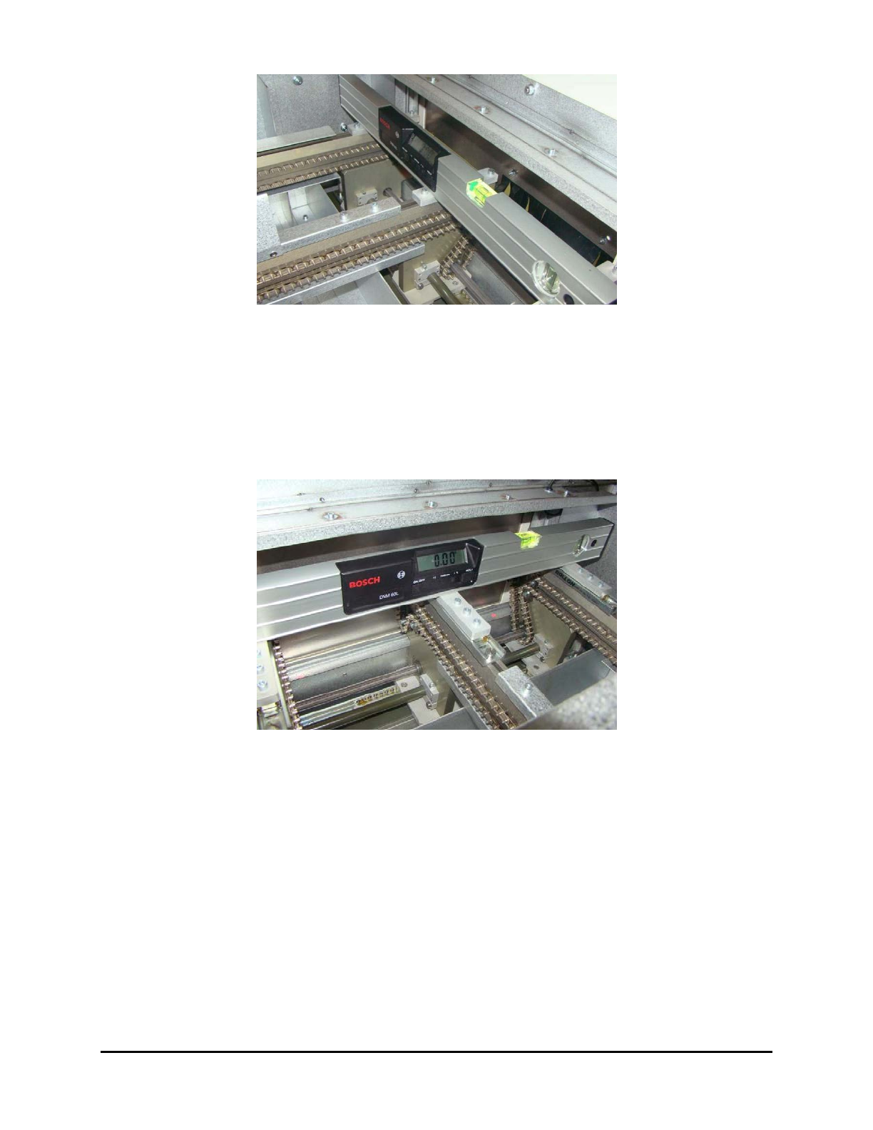
Figure 3-4 System Leveling – Conveyor Entrance
6. Observe the position of the bubble within the level’s window. The bubble should be
centered indicating the UV-9 Cure Module is level front-to-back.
7. If necessary, adjust the levelers (feet) described in Step 4.
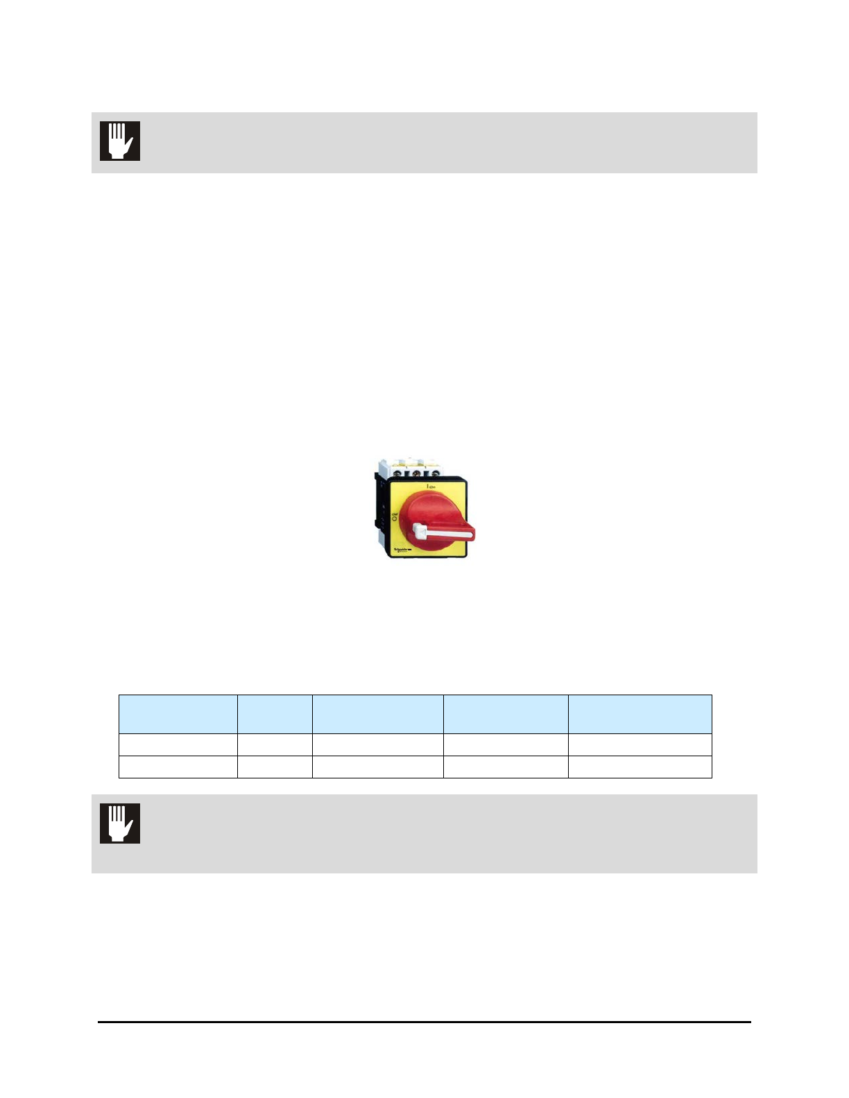
8. Place the level at the conveyor exit, with one end of the level on the front rail and the other
end on the back rail (Figure 3-5).
Figure 3-5 System Leveling – Conveyor Exit
9. Observe the position of the bubble within the level’s window. The bubble should be
centered indicating the UV-9 Cure Module is level from front-to-back.
10. If necessary, adjust the levelers (feet) described in Step 4.
11. Check for all-around stability by pressing down on a top corner of the UV-9 Cure Module.
If one leveler is lower or higher than the others, the cure module will rock back and forth.
Adjust the levelers so that they are all bearing the weight equally.
12. Re-level the UV-9 Cure Module from side-to-side and from front-to-back, if necessary.
13. Re-tighten all four (4) locking nuts when the machine has been completely leveled and
stabilized.
NOTE Do not over tighten the locking nuts. They only need to be snug.
Installation 3-5
3.8 Connecting the Power
CAUTION! This procedure should only be performed by a trained service technician.
Tools and Materials Needed:
• Facility Main Power and Ground Cables
• Key to Electronics Enclosure
To connect the power cables:
NOTE The main power inlet must be directly connected to the main switch inside the electrical
cabinet.
1. Ensure the facility power switch is locked out and tagged out. See 2.12 Lockout/Tagout of
Electrical Energy.
2. Turn the Main Power Switch located at the back of the UV Cure Module to the
OFF (0)
position.
Figure 3-6 Main Power Switch
3. If necessary, unlock the electronics enclosure door (Figure 1-1) using the key provided.
4. Install a circuit breaker on the main power inlet to isolate the oven during maintenance.
Table 3-1 Circuit Breaker Specifications
Circuit
Breaker
Recommended
Cable Section
Recommended
Cable Length
Differential
One UV module 20A 4mm² / AWG10 10 meters + GFCI over 100 mA
Two UV modules 32A 6mm² / AWG8 10 meters + GFCI over 100 mA
CAUTION! The UV-9 Cure Module and Upstream/Downstream equipment must be properly
grounded.
3-6 Installation
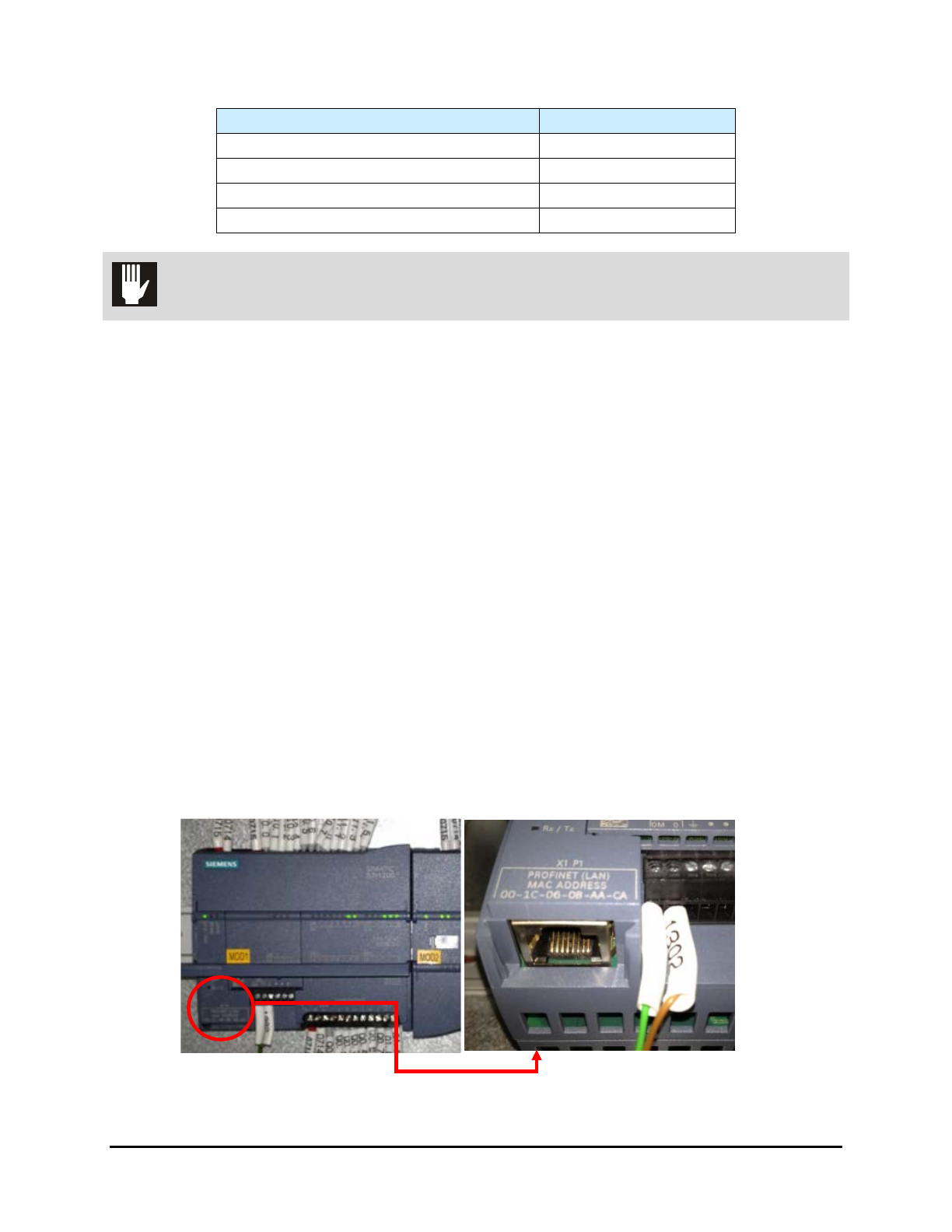
Table 3-2 Electrical Specifications
Characteristic
Voltage 400Vac
Installed Power Top lamp (kW) 7
Installed Power Top and Bottom Lamp (kW) 14
Mode N+EARTH, TT or TN
CAUTION! The UV-9 Cure Module is not compatible with Neutral IT.
5. Feed the facility power cable through the main power inlet on the rear panel of the UV-9.
6. Locate and connect facility power cable leads to the Main Circuit Breaker and the green
ground lead to the ground terminal.
7. Close and lock the electronics enclosure door.
8. Turn the Main Power Switch to the
ON (I) position.
9. Remove all locks and tags from facility power and turn the power ON.
3.9 Connecting SMEMA Cables
To connect the SMEMA cables:
1. Locate the upstream and downstream SMEMA communication cables and connect them to
the SMEMA communication ports on the rear panel of the UV-9 Cure Module.
2. Connect the other end of the cables to the SMEMA communications ports on the upstream
and downstream machines.
3.10 Connecting the PLC to Upstream Equipment
It is necessary (unless the UV-9 Cure Module has a touch screen) to connect the PLC to the computer of
the upstream equipment. An Ethernet cable is provided with the UV-9 for this purpose. See Figure 3-7.
Figure 3-7 PLC Connection
Installation 3-7