UV-9+Cure+Module+7269348_B+Manual.pdf - 第84页
5.7.4.5 S MEMA Screen The SMEMA screen d isplays the v arious SMEMA rel ated setpoints. S elect the SMEMA button on the "My Oven" menu t o open this scre en. Name Description Pcb Interval Time interval between …
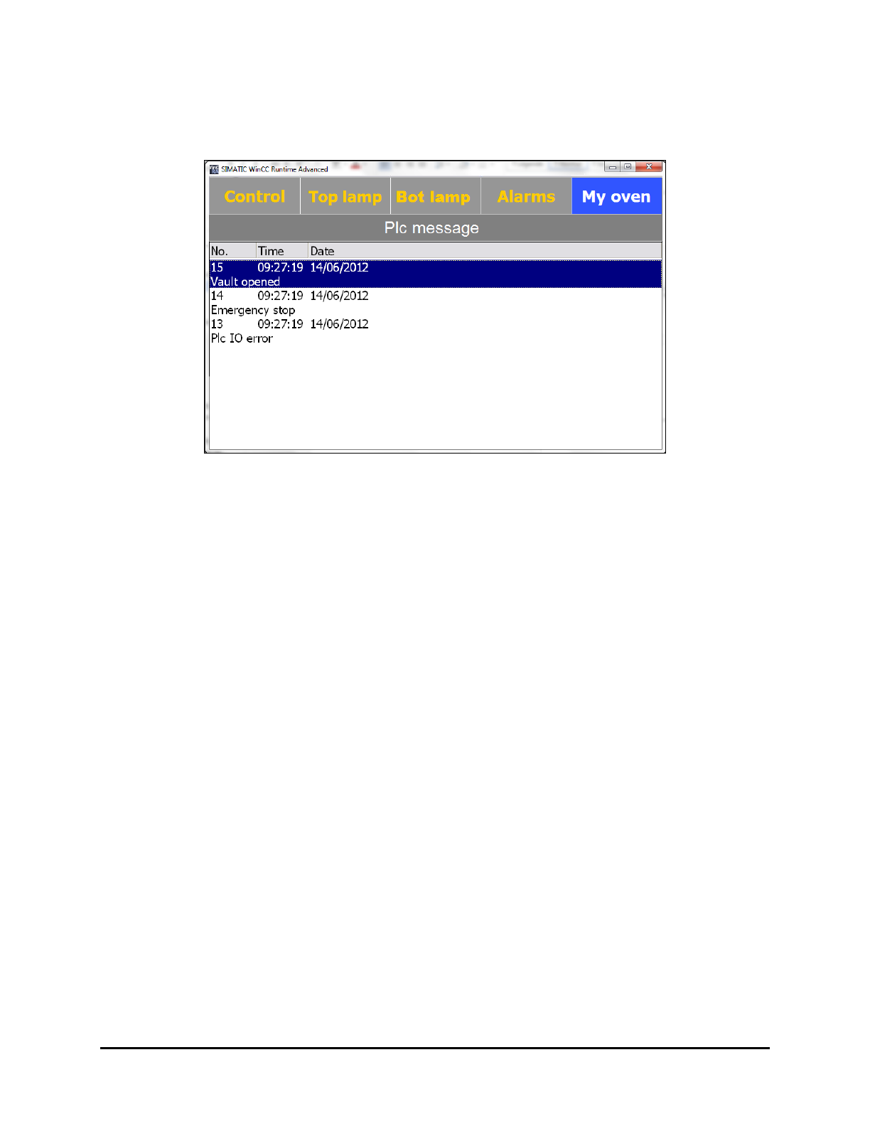
5.7.4.4 PLC Message Screen
The PLC Messages screen displays the messages of the lane controller that are generated during oven
operation. Select the
Message button the "My Oven" menu to open this screen.
Figure 5-21 PLC Message Screen
Operation 5-21
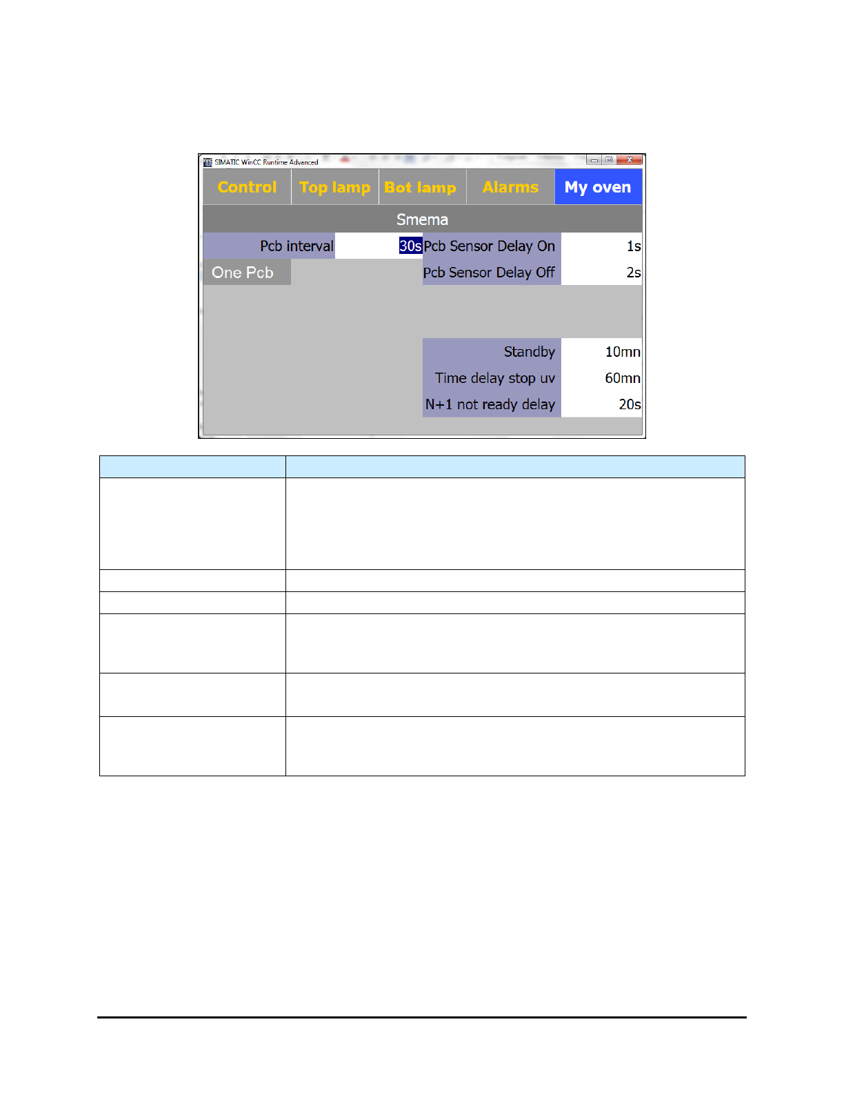
5.7.4.5 SMEMA Screen
The SMEMA screen displays the various SMEMA related setpoints. Select the SMEMA button on the
"My Oven" menu to open this screen.
Name Description
Pcb Interval
Time interval between boards (even if the Upstream Available signal
is on).
Note: this feature is active only if ONE PCB is not active (grayed out). If
one PCB is active, the oven will not accept a new board until the
previous board has exited.
Pcb Sensor Delay On (s)
Delay time before attempting to detect a board at the oven entrance.
Pcb Sensor Delay Off (s)
Delay time before attempting to detect a board at the oven exit.
Standby (mn)
Displays the standby setpoint.
The maximum time without board detection before entering Standby
Mode.
Time delay stop UV (mn)
Displays the Time Delay Stop UV setpoint.
The maximum time without board detection before oven stops.
N-1 not ready (s)
Displays the N-1 not ready setpoint.
The maximum time without a signal from the downstream equipment
before the alarm sounds.
Figure 5-22 SMEMA Screen
5-22 Operation
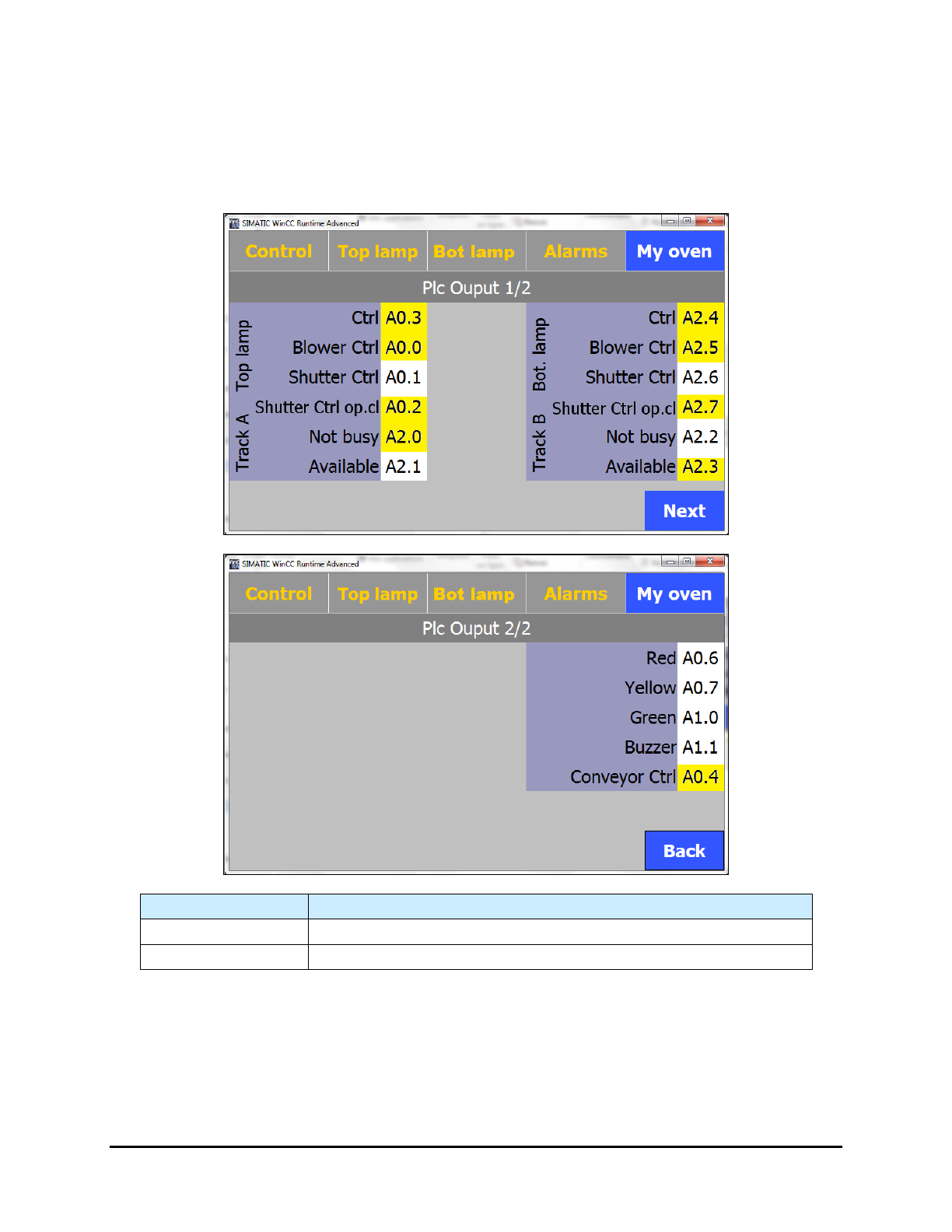
5.7.4.6 PLC Output Screens
The PLC Output screens display the active/inactive status of the outputs. Select the Output PLC button
on the "My Oven" menu to open this screen.
NOTE The background of the outputs is yellow when they are active.
Name
Description
Next
Proceeds to Page 2 of the PLC Output screen.
Back
Returns to Page 1 of the PLC Output screen.
Figure 5-23 PLC Output Screens
Operation 5-23