UV-9+Cure+Module+7269348_B+Manual.pdf - 第44页
3.11 Connecting the Ex haust Tools and Materials Needed • 254 mm ( 10 in.) Duct • Exhaust Blower • Auxiliary Fan (i f duct is over 5 m eters i n length) To connect the exhaust duct: NOTE The customer m ust provide the …
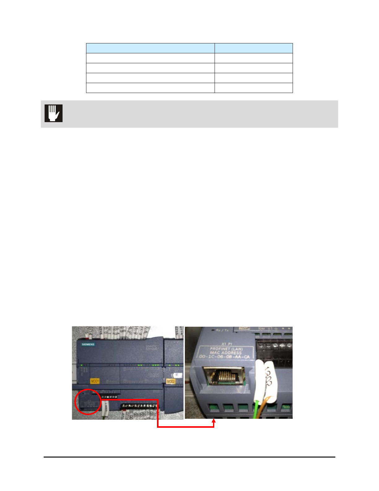
Table 3-2 Electrical Specifications
Characteristic
Voltage 400Vac
Installed Power Top lamp (kW) 7
Installed Power Top and Bottom Lamp (kW) 14
Mode N+EARTH, TT or TN
CAUTION! The UV-9 Cure Module is not compatible with Neutral IT.
5. Feed the facility power cable through the main power inlet on the rear panel of the UV-9.
6. Locate and connect facility power cable leads to the Main Circuit Breaker and the green
ground lead to the ground terminal.
7. Close and lock the electronics enclosure door.
8. Turn the Main Power Switch to the
ON (I) position.
9. Remove all locks and tags from facility power and turn the power ON.
3.9 Connecting SMEMA Cables
To connect the SMEMA cables:
1. Locate the upstream and downstream SMEMA communication cables and connect them to
the SMEMA communication ports on the rear panel of the UV-9 Cure Module.
2. Connect the other end of the cables to the SMEMA communications ports on the upstream
and downstream machines.
3.10 Connecting the PLC to Upstream Equipment
It is necessary (unless the UV-9 Cure Module has a touch screen) to connect the PLC to the computer of
the upstream equipment. An Ethernet cable is provided with the UV-9 for this purpose. See Figure 3-7.
Figure 3-7 PLC Connection
Installation 3-7
3.11 Connecting the Exhaust
Tools and Materials Needed
• 254 mm (10 in.) Duct
• Exhaust Blower
• Auxiliary Fan (if duct is over 5 meters in length)
To connect the exhaust duct:
NOTE The customer must provide the exhaust blower and associated ductwork.
1. Install the facility ventilation duct on the UV-9 Cure Module exhaust port and clamp in place.
The UV-9 Cure Module has one internal blower per module. The internal blower is
sufficient if the duct length from the UV-9 toward the outside is under 5 meters.
2. If the duct is over 5 meters in length, install an auxiliary fan.
Table 3-3 lists internal and extraction exhaust flow rates.
Table 3-3 Exhaust Flow Rates
Exhaust
1 lamp (m
3
/h)
Exhaust
2 lamps (m
3
/H)
UV-9 Cure Module
(internal blowers)
0-450
± 15%
0-900
± 15%
Extraction flow rate in UV-9
facility exhaust duct
550
± 5%
1100
± 5%
NOTE The extraction flow rate must be measured in the UV-9 exhaust duct with the UV-9 Cure
Module on and at full power.
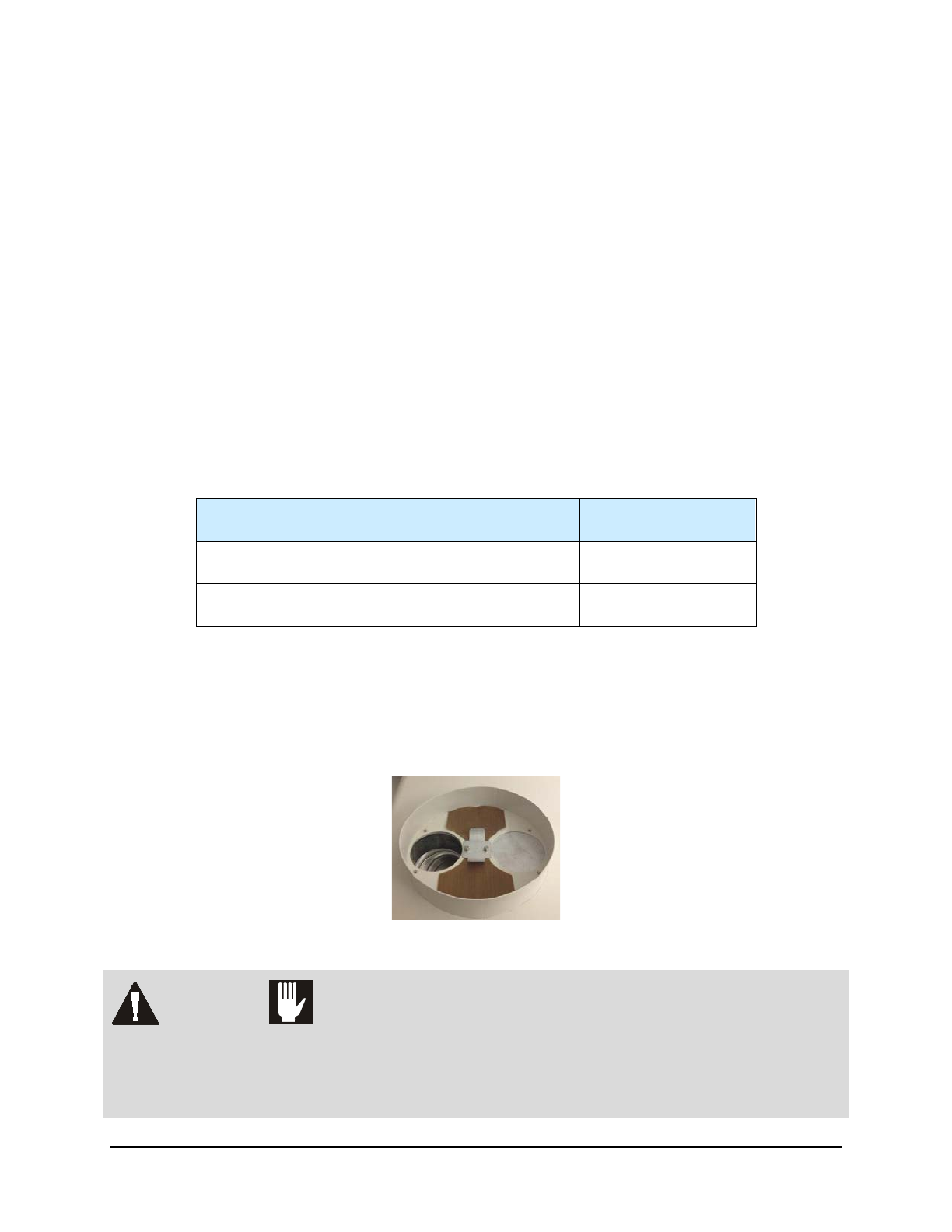
Sufficient exhaust flow is required to cool the UV lamp. The internal blowers are driven by an inverter to
adjust the cooling. Two flaps, mounted next to the exhaust port, operate as a differential to ensure proper
cooling to the UV source. Make sure not to block the flaps. They must move freely.
Figure 3-8 Exhaust Port
WARNING! CAUTION!
An external dry contact is required. This dry contact must be positive for
extraction and negative when it is turned off. An insufficient extraction flow rate
can cause a lamp default and components to overheat. If an external contact is not
used, the warranty is null and void.
3-8 Installation
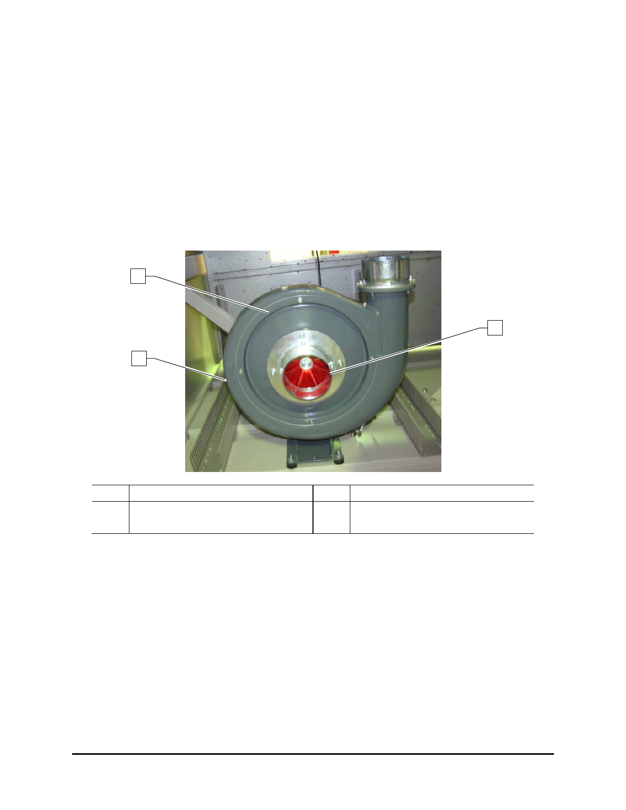
3.11.1 Exhaust Fan Rotation Direction
To check the rotation direction:
1. Disconnect the blower hose to see the impeller (Figure 3-9).
2. Turn the Main Power Switch located at the back of the UV Cure Module to the
ON (l)
position.
3. Press the relay KM3 inside the electrical cabinet.
4. Verify that rotation matches the direction of the arrow.
5. After confirming proper rotation, turn the Main Power Switch to the
OFF position (0).
6. Reconnect the blower hose.
Item
Description
Item
Description
1 Exhaust Pump 3 Impeller
2 Direction of Rotation Arrow
Figure 3-9 Exhaust Pump
1
2
3
Installation 3-9