UV-9+Cure+Module+7269348_B+Manual.pdf - 第48页
3.15 Initial Startup CAUTION! Only qualified technician s trained by Nords on ASYMTEK should perform initial startup, oth erwise the warranty could be null/vo id . For daily production, i t is import ant to follow the or…
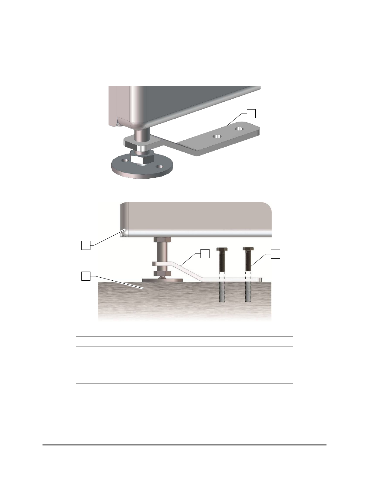
3.14 Anchoring the Oven
To prevent movement that could cause injury to personnel and damage to the cure module and facility,
each cure module leveler (foot) should be anchored to the floor with two bolts (Figure 3-11 and
Figure 3-12). The anchor joint (the point between each anchor bolt and the floor) must be able to
withstand at least 220 lbs (100 kg) of pullout force.
Figure 3-11 Seismic Brackets
Item Description
1 Cure Module
2 Leveler
3 Seismic Bracket
4 Anchor Bolts
Figure 3-12 Anchoring the UV-9 Cure Module
2
1
3
4
3
Installation 3-11

3.15 Initial Startup
CAUTION! Only qualified technicians trained by Nordson ASYMTEK should perform initial
startup, otherwise the warranty could be null/void.
For daily production, it is important to follow the order described in this manual to prevent:
• The "safety mode", which will delay the operational mode of the oven.
• The damage of equipment over the long term.
NOTE As a precaution, the UV lamp is not pre-installed at the factory. It will be installed on-site
by the Nordson ASYMTEK technician. See 6.5.2 UV Lamp Replacement.
1. Verify the following before initial start up:
a. The facility electrical network is compatible with the UV-9 Cure Module electrical
requirements. The UV-9 must be TT or NT.
The UV-9 is NOT compatible with neutral IT.
b. The main electrical power is connected. See 3.8 Connecting the Power.
c. The Main Power Switch, located at the rear of the equipment, is in the
ON position (I).
d. The SMEMA cables are connected to the ports on the rear panel of the UV-9 Cure
Module. See 3.9 Connecting SMEMA Cables.
e. The system exhaust is connected to the facility exhaust and the customer-supplied flow
safety switch operates correctly. See 3.11 Connecting the Exhaust.
f. The rotation direction of the blower motor located at the rear of the electrical cabinet.
An arrow on the blower body indicates the rotation direction. If necessary, invert two
(2) phases on the Main Power Switch. See 3.11.1 Exhaust Fan Rotation Direction.
g. The UV-9 Cure Module is level.
2. Make sure the E-Stop button is not activated.
If it is activated, turn the button clockwise until it pops out.
3. Press the green
ON button on the Control Panel to power on the unit (Figure 3-13).
NOTE Pressing the green ON button does not turn on the oven. You must press the black
Start/Stop button for one (1) second to turn on the oven. You can also start the oven
through the software. See 5.5.2 Starting the Oven.
3-12 Installation
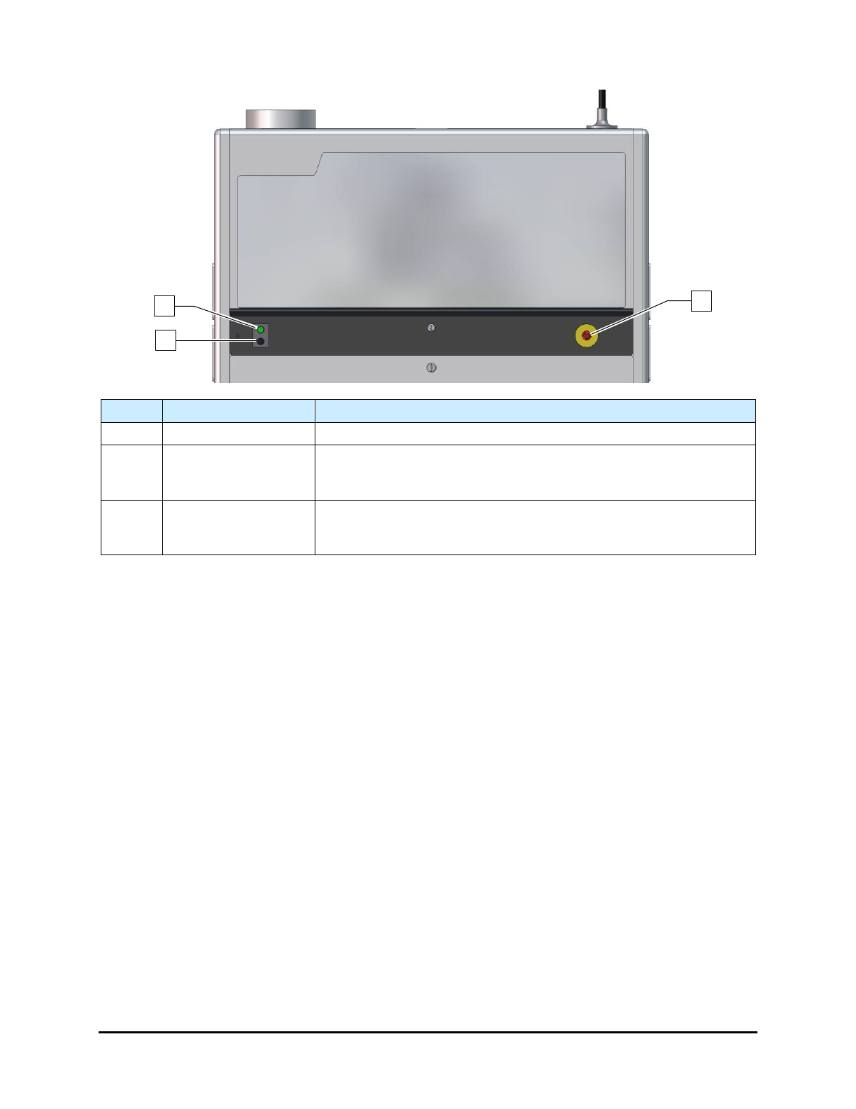
Item Name Description
1 ON Button (Green)
The
ON
button powers on the UV-9 Cure Module.
2
Start/Stop Button
(Black)
The Start/Stop button (Black) turns the oven on and off. To start the
over, press the black button for one (1) second. To stop the oven,
press the black button for five (5) seconds.
3
EMO Button
(Emergency Stop)
In the event of an emergency or malfunction, press the E-Stop
button. Activating the E-Stop immediately halts conveyor movement
and turns off the UV oven. See 2.10 Emergency Shutdown.
Figure 3-13 Control Panel
3.16 Shut Down
1. Press the Start/Stop button for five (5) seconds.
2. To isolate the oven from the main power source, turn the Main Power Switch located on the
rear of the equipment to the
OFF position (0).
NOTE Perform a lock out/tag out procedure during maintenance. See 2.12 Lockout/Tagout of
Electrical Energy for more details.
3.17 Emergency Shut Down
In the event of an emergency or malfunction, press the E-Stop button. The UV-9 Cure Module has two E-
Stop buttons. The E-Stop buttons are the large red buttons located on the operator’s front control panel
(Figure 3-13) and one at the rear of the oven (Figure 2-5). Activating the E-Stop immediately halts
conveyor movement and turns off the UV oven. See 2.10 Emergency Shutdown.
1
2
3
Installation 3-13