UV-9+Cure+Module+7269348_B+Manual.pdf - 第40页
3.7 Leveling t he UV -9 Cure Module CAUTION! This proce dure should only be perf ormed by a tra ined servic e technicia n. Tools and Materials Needed: • Adjustable Wren ch • Level To level the oven in the production line…
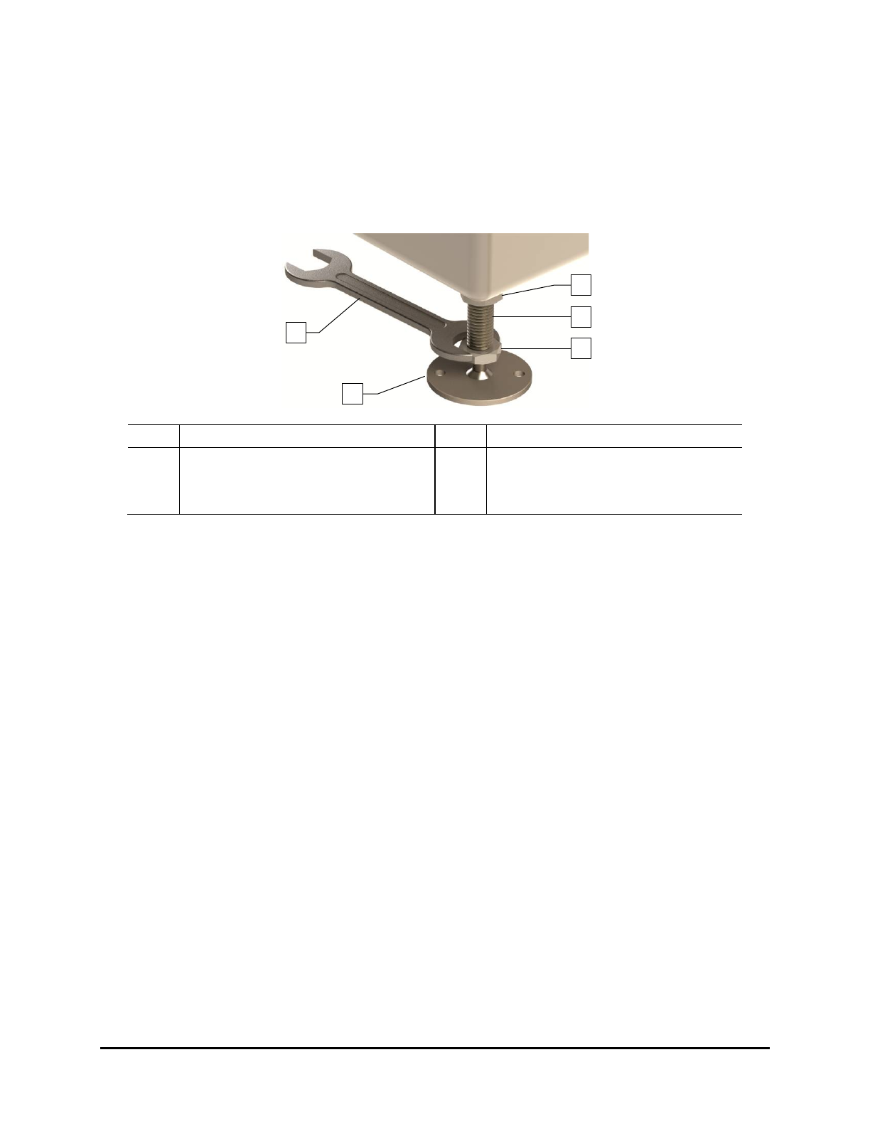
7. Raise or lower each leveler (foot) as follows until they all touch the floor:
a. Loosen the 1½-inch lock nut on the leveler. See Figure 3-2.
b. Adjust the 1½-inch post nut to raise or lower each leveler as required.
Turning the post nut clockwise raises the leveler. Turning the post nut
counterclockwise lowers the leveler.
c. Tighten the lock nut finger tight.
Item
Description
Item
Description
1 Lock Nut 4 Leveler (foot)
2 Post 5 1 1/2-inch Wrench
3 Post Nut
Figure 3-2 Adjusting the Levelers
3.6 Unpacking the Accessories
The accessories received will vary depending upon the configuration of your UV-9 Cure Module. These
accessories may include UV lamps, power supplies, power cords, tool and maintenance kits, and
equipment manuals. They may be in a crate, plastic wrapped on a skid, or secured on the cure module.
Tools and Materials Needed:
• Flat Bar
• Appropriate Personal Protective Equipment
• Pen or Pencil
To unpack the accessories:
1. Locate the shipping list and place it in a safe location.
2. If the accessories were shipped in a wooden crate, use the flat bar and hammer to remove
the crate lid.
3. As you uncrate or unwrap each item, identify it, and place a check mark next to the item
name on the shipping list.
If any parts or accessories are missing, please contact Nordson ASYMTEK Technical
Support.
1
5
4
3
2
Installation 3-3
3.7 Leveling the UV-9 Cure Module
CAUTION! This procedure should only be performed by a trained service technician.
Tools and Materials Needed:
• Adjustable Wrench
• Level
To level the oven in the production line:
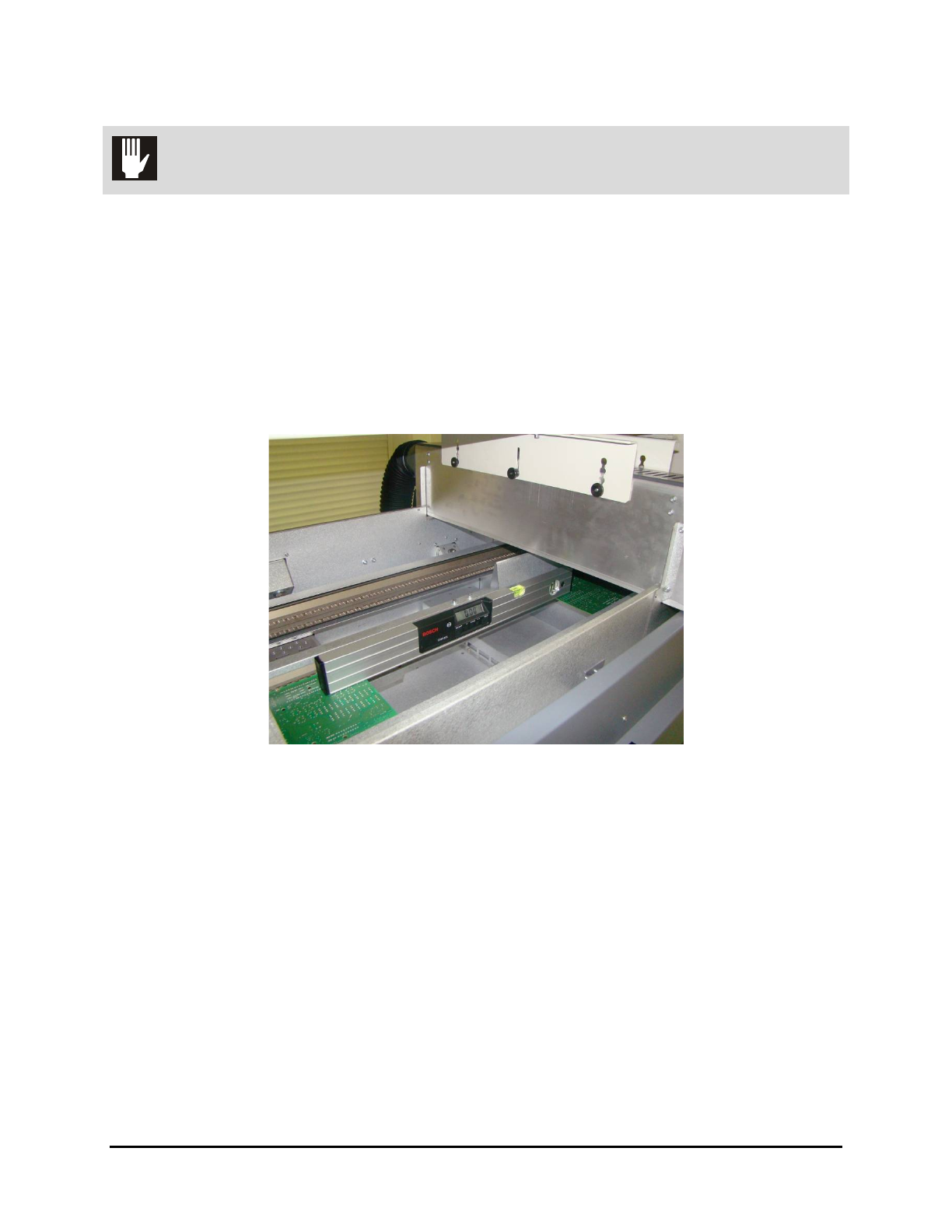
1. Open the hood and place the level in the center of the front conveyor rail, along the length
of the rail (Figure 3-3).
2. Remove the tunnel modules for access to the conveyors.
Figure 3-3 System Leveling – Left to Right
3. Observe the position of the bubble within the level’s window. The bubble should be
centered indicating the UV-9 Cure Module is level from side-to-side.
4. If necessary, adjust the levelers (feet) as follows:
a. Loosen the 1½-inch lock nut on the leveler. See Figure 3-2.
b. Adjust the 1½-inch post nut to raise or lower each leveler direction until the level’s
bubble is centered, indicating that the system is level from side-to-side.
Turning the post nut clockwise raises the system. Turning the post nut
counterclockwise lowers the system.
c. Tighten the lock nut finger tight.
5. Place the level at the conveyor entrance, with one end of the level on the front rail and the
other end on the back rail (Figure 3-4).
3-4 Installation
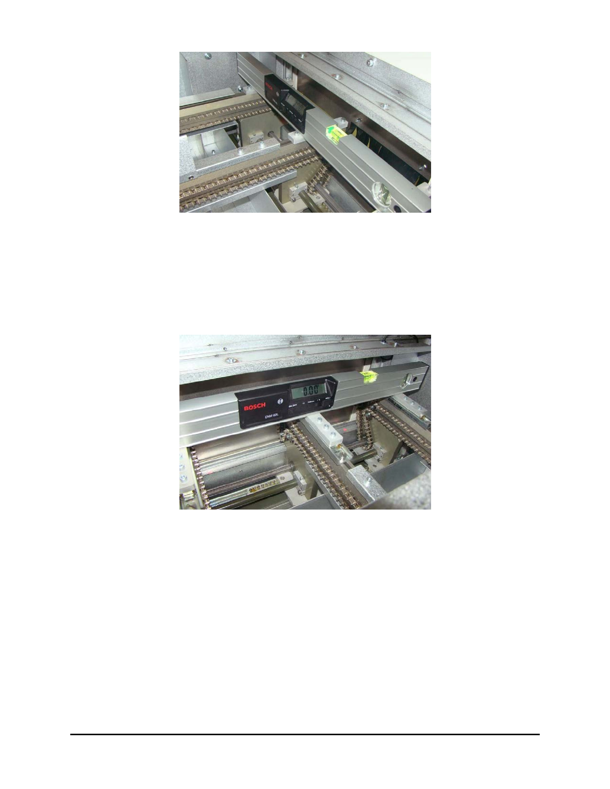
Figure 3-4 System Leveling – Conveyor Entrance
6. Observe the position of the bubble within the level’s window. The bubble should be
centered indicating the UV-9 Cure Module is level front-to-back.
7. If necessary, adjust the levelers (feet) described in Step 4.
8. Place the level at the conveyor exit, with one end of the level on the front rail and the other
end on the back rail (Figure 3-5).
Figure 3-5 System Leveling – Conveyor Exit
9. Observe the position of the bubble within the level’s window. The bubble should be
centered indicating the UV-9 Cure Module is level from front-to-back.
10. If necessary, adjust the levelers (feet) described in Step 4.
11. Check for all-around stability by pressing down on a top corner of the UV-9 Cure Module.
If one leveler is lower or higher than the others, the cure module will rock back and forth.
Adjust the levelers so that they are all bearing the weight equally.
12. Re-level the UV-9 Cure Module from side-to-side and from front-to-back, if necessary.
13. Re-tighten all four (4) locking nuts when the machine has been completely leveled and
stabilized.
NOTE Do not over tighten the locking nuts. They only need to be snug.
Installation 3-5