UV-9+Cure+Module+7269348_B+Manual.pdf - 第58页
4.9 External UV Shutters Adjustme nt The openings at the entrance and exit o f the UV - 9 Cure Module can be adjusted to accommodate the thicknesses of th e boards being cured . To adjust the external UV shutters: 1. Loo…
4.8 Internal UV Radiation Traps Adjustment
The UV-9 Cure Module tunnel is equipped with light traps to reduce the light reflections inside the
tunnel.
They are located as follows:
• Light traps under UV module
• Light traps under tunnel
• Light traps conveyor shields
• UV module light traps
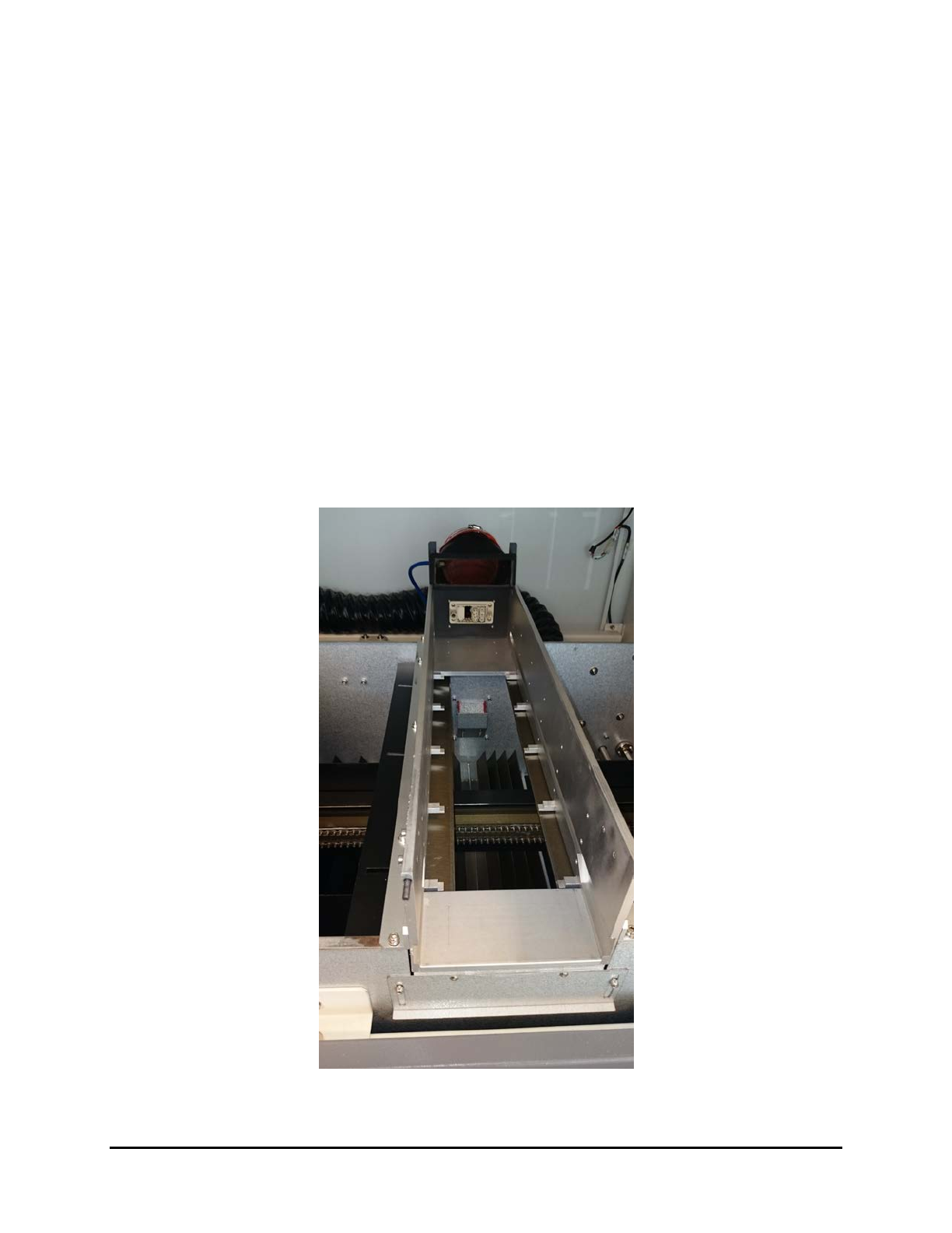
The light traps on the top module are the only adjustable light traps (Figure 4-8). They can be adjusted
horizontally or vertically to reduce the low irradiance beams on the substrate (<15 mW). These low
irradiance beams can have a direct impact on the process and the quality of the curing (physical aspect of
the coating). Blocking the low irradiance beam reduces the difference in the behavior between the true
cure and the surface cure.
NOTE Changing the setting of the light traps, may have an impact on the closed loop calibration
(does not impact the high point of irradiance, but the total dose).
Figure 4-8 Light Traps – UV Module
Adjustments 4-7
4.9 External UV Shutters Adjustment
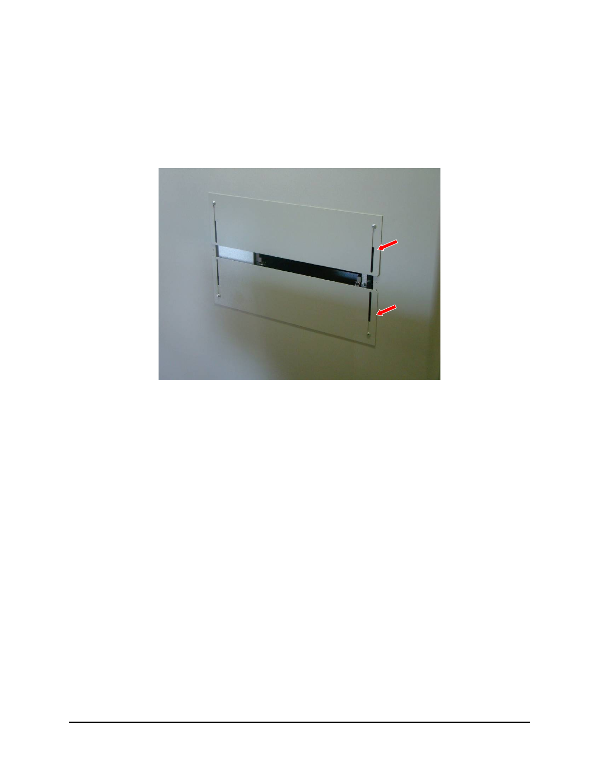
The openings at the entrance and exit of the UV-9 Cure Module can be adjusted to accommodate the
thicknesses of the boards being cured.
To adjust the external UV shutters:
1. Loosen the screws and slide the shutters up or down according to the component’s height
(Figure 4-9).
Figure 4-9 External UV Shutters
2. Tighten the screws after adjustment.
NOTE A sliding shutter automatically closes off the free space to the rear of the adjustable
conveyor rail.
4-8 Adjustments
4.10 UV Lamp Power Adjustment
4.10.1 Oven with Open Loop (Manual) Regulation
At the startup of the oven or after a lamp replacement, the emitted radiation of the UV lamp must be
checked with a Power Puck
® or radiometer with a valid calibration certificate.
To adjust the UV lamp power:
1. From the technical specification sheet of the UV product, determine the conveyor speed and
the UV power required for the UV product curing.
2. Disable the Process Time Control option. See 5.7.4.8 Process Time Control.
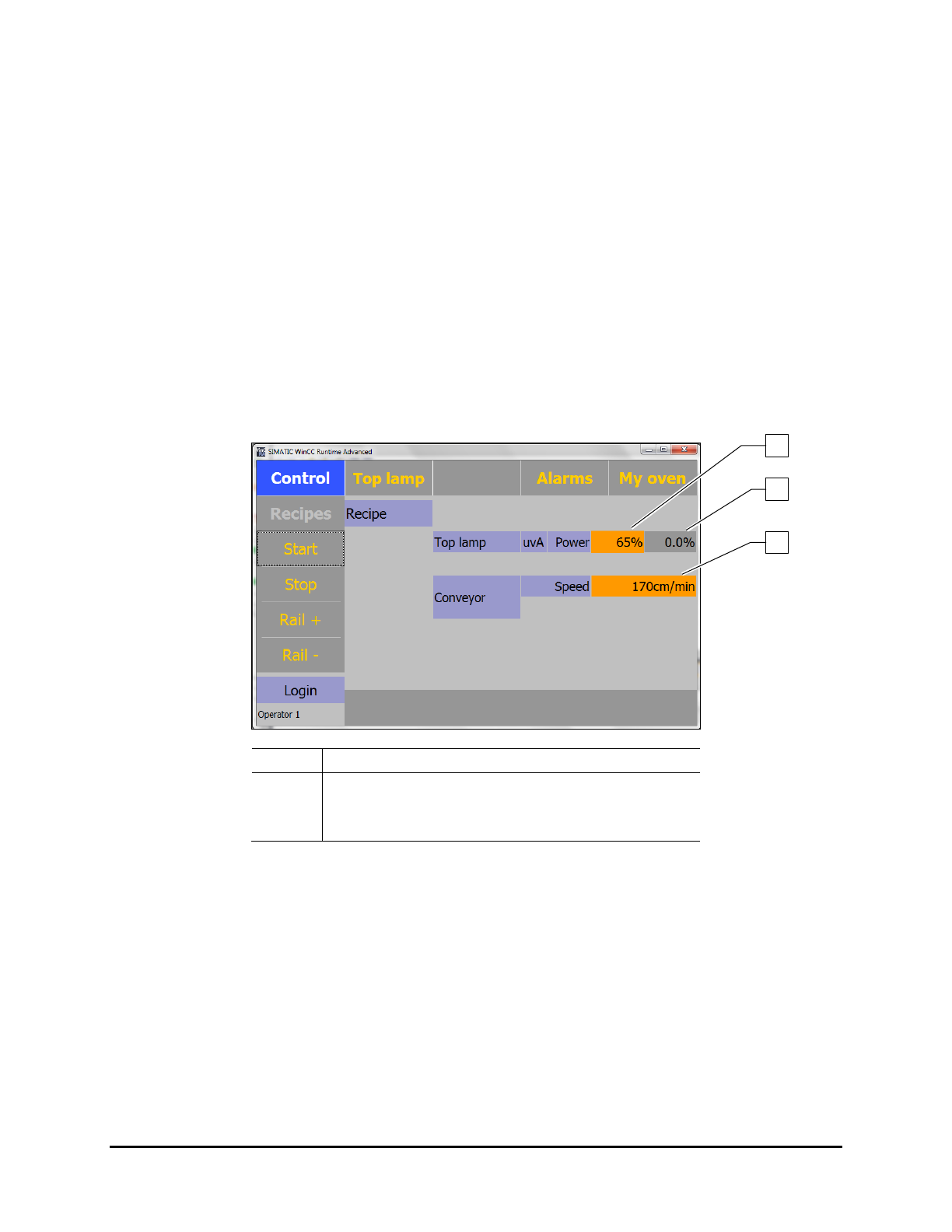
3. Set the output power and check with a Power Puck.
The output is entered in % is in the Control Screen.
Perform the measurements with a cold radiometer. An internal temperature increase of
the UV power recorder corrupts the measurement.
Item
Description
1 Set Output Power
2
Actual Delivered Power
3 Set Conveyor Speed
Figure 4-10 Setting the Output Power (Open Loop)
4. Perform curing tests.
5. When curing is correct, record the following parameters for future use:
The output power of the lamps.
The values in mJ given by the Power Puck.
6. Re-enable the Process Time Control option. See 5.7.4.8 Process Time Control.
7. Every 120 hours, check and adjust the output power accordingly.
8. Replace the UV lamp when the output power reaches 100%.
NOTE The accuracy of a Power Puck is + /- 10%, typically + /- 5%.
1
3
2
Adjustments 4-9