drt2_devicenet_q102-e1_20_22_csm2147.pdf - 第104页
84 Analog I/O Unit s GT1-AD/DA Dimensions (Unit: mm) Wiring Diagrams GT1-AD08MX GT1-D A04MX GT1-AD04 GT1-D A04 110 37.4 27.6 4 65 12.6 35 60 Note: Accessory cable included. GT1-AD08MX GT1-D A04MX (Molex Connector Models)…
Analog I/O Units GT1-AD/DA 83
Analog I/O Units
GT1-AD/DA
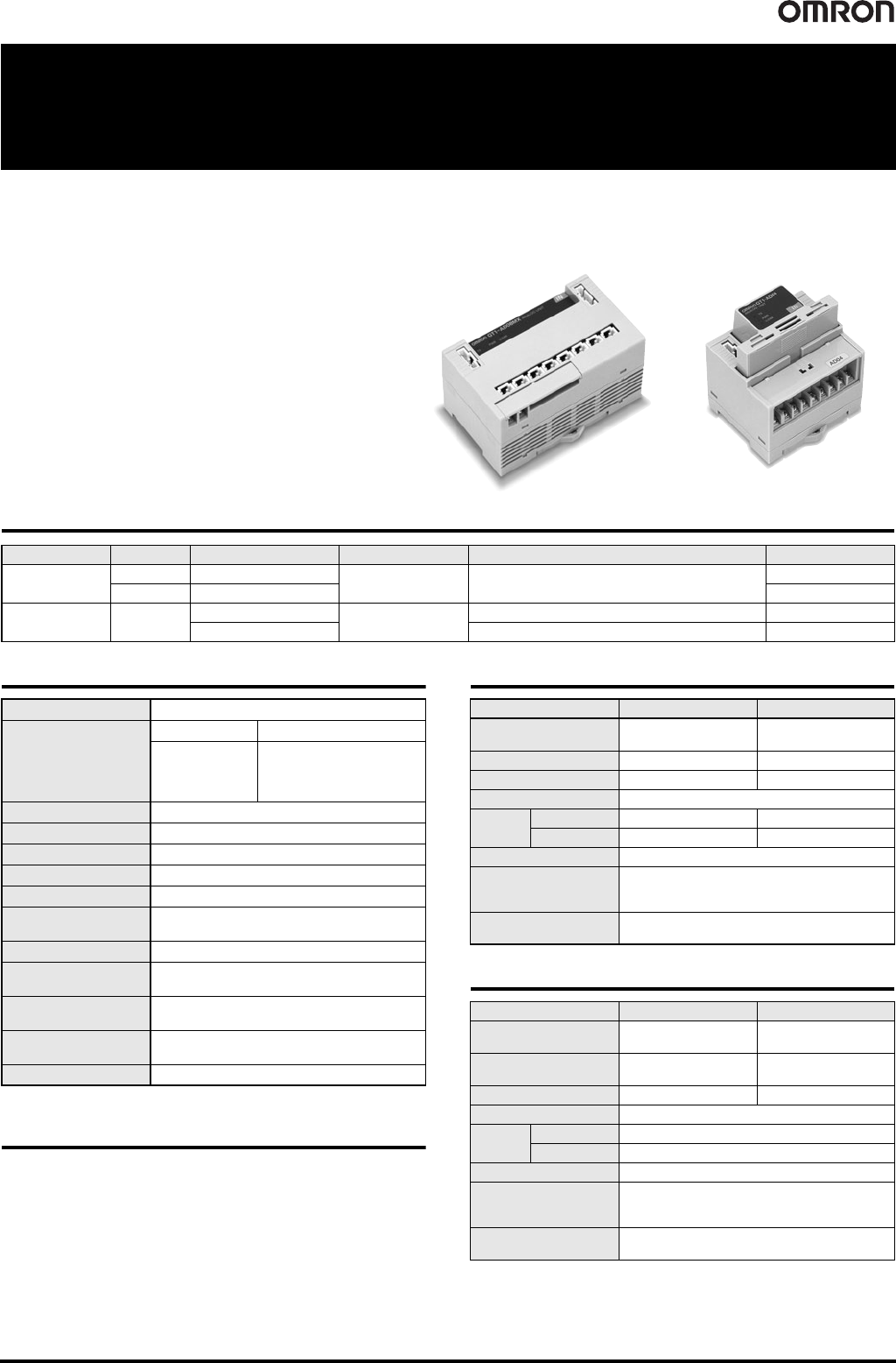
Analog Input/Output Units Compatible with MULTIPLE I/O
TERMINAL
• Input block incorporates connectors that can be easily
mounted or dismounted. (GT1-AD08MX, GT1-DA04MX)
• 8 or 4 inputs.
• 4 outputs.
• High resolution of 1/6,000.
• High conversion speed of 8 ms/8 points or 4 ms/4 points.
• DIN track mounting.
Ordering Information
General Specifications
* Power for analog I/O is provided from the internal power supply.
Applicable Connector
Note: Refer to page 144 for Peripheral Devices.
Input Specifications
Output Specifications
Connector model Terminal Block Model
I/O classification I/O points I/O connections Power supply voltage I/O specification Model
Analog input
8 Molex connector
24 VDC
4 to 20 mA, 0 to 20 mA, 0 to 5 V, 1 to 5 V,
0 to 10 V, -10 to 10 V
GT1-AD08MX
4 Terminal block GT1-AD04
Analog output 4
Molex connector
24 VDC
0 to 5 V, 1 to 5 V, 0 to 10 V, -10 to 10 V GT1-DA04MX
Terminal block 0 to 5 V, 1 to 5 V, 0 to 10 V, -10 to 10 V, 4 to 20 mA GT1-DA04
I/O power supply voltage 20.4 to 26.4 VDC (24 VDC -15%/+10%) *
Current consumption
I/O Unit interface Internal circuitry power supply
50 mA max.
GT1-AD08MX: 100 mA max.
GT1-AD04: 100 mA max.
GT1-DA04MX: 100 mA max.
GT1-DA04: 150 mA max.
Noise immunity Conforms to IEC 61000-4-4, 2 kV (power line)
Vibration resistance 10 to 150 Hz, 1.0-mm double amplitude or 70 m/s
2
Shock resistance 200 m/s
2
Dielectric strength 500 VAC
Mounting method DIN 35 mm-track mounting
Mounting strength
No damage when 100 N pull load was applied in all
directions (10 N min. in the DIN track direction)
Terminal strength No damage when 100 N pull load was applied
Ambient operating
temperature
-10°C to 55°C
Ambient operating
humidity
25% to 85% (with no condensation)
Ambient storage
temperature
-25°C to 65°C
Accessories I/O Unit Connecting Cable (40 mm)
Item Specifications Voltage input Current input
Input type
0 to 5 V, 1 to 5 V,
0 to 10 V, -10 to 10 V
0 to 20 mA, 4 to 20 mA
Maximum signal input ± 15V ± 30 mA
Input impedance 1M min. Approx. 250
Resolution 1/6,000 (FS)
Overall
accuracy
25°C ±0.3% FS ±0.4% FS
-10°C to 55°C ±0.6% FS ±0.8% FS
Conversion speed 8 ms/8 points, 4 ms/4 points
Conversion output data
Binary data
-10 to 10-V range: F448 to 0BB8 full scale
Other signal ranges: 0000 to 1770 full scale
Insulation method
Transistor or photocoupler insulation between inputs
and power lines.
Item Specifications Voltage output Current output
Output type
0 to 5 V, 1 to 5 V,
0 to 10 V, -10 to 10 V
4 to 20 mA
Output permissible load
resistance
5k min. 600 max.
Output impedance 0.5 max. --
Resolution 1/6,000 (FS)
Overall
accuracy
25°C ±0.4% FS
-10°C to 55°C ±0.8% FS
Conversion speed 4 ms/4 points
DA output data
Binary data
-10 to 10 V range: F448 to 0BB8 full scale
Other signal ranges: 0000 to 1770 full scale
Insulation method
Transistor or photocoupler insulation between
outputs and power lines.
84 Analog I/O Units GT1-AD/DA
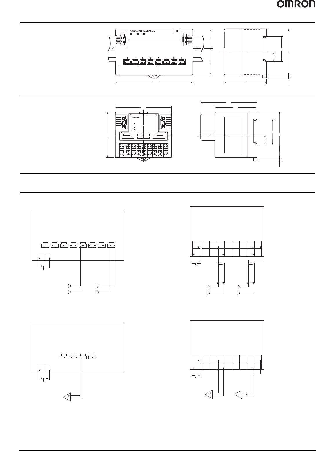
Dimensions (Unit: mm)
Wiring Diagrams
GT1-AD08MX
GT1-DA04MX
GT1-AD04
GT1-DA04
110
37.4
27.6
4
65
12.6
35
60
Note: Accessory cable included.
GT1-AD08MX
GT1-DA04MX
(Molex Connector Models)
GT1-AD04
80
65
80
60
4
65
12.6
35
GT1-AD04
GT1-DA04
(Terminal Block Models)
Note: Accessory cable included.
Voltage input Current input
0 V 0 V
Input
01234567
24 VDC
internal circuit
power supply
VG
External
device
Output
0123
24 VDC
internal circuit
power supply
VG
24 VDC
internal circuit
power supply
Voltage input
0 V
Current input
(Short the V+ and I+ terminals for a current input.)
0 V
AG
V+
3
I+
3
–
3
AG
V+
2
I+
2
–
2
AG
V+
1
I+
1
–
1
AG
V+
0
I+
0
–
0
+
–
Voltage output Current output
External
device
External
device
24 VDC
internal circuit
power supply
NC
V+
3
I+
3
–
3
NC
V+
2
I+
2
–
2
NC
V+
1
I+
1
–
1
NC
V+
0
I+
0
–
0
+
–
Temperature Input Units GT1-TS04@ 85
Temperature Input Units
GT1-TS04@
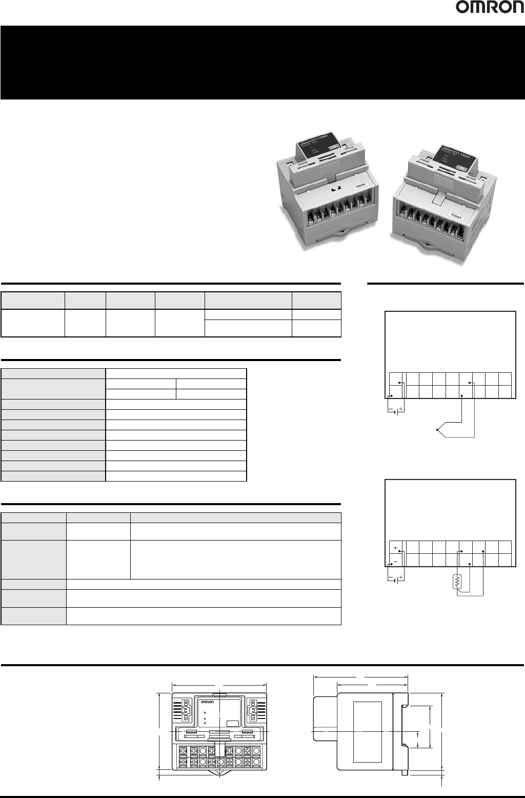
Temperature Input Units for use with MULTIPLE I/O TERMINAL
• Four inputs.
• Thermocouples and platinum resistance thermometer models
are available.
• Conversion time is only 250 ms for 4 inputs.
• The Configurator can be used to calibrate temperatures.
• The circuit section can be removed, so rewiring isn’t required
during maintenance.
• DIN track mounting.
Dimensions (Unit: mm)
Ordering Information
General Specifications
Input Specifications
* K or T below -100°C: +2°C ±1 digit max. L: ±2°C ±1 digit max.
R or S below 200°C: ±3°C ±1 digit max. B below 400°C: No standard set
I/O classification I/O points
I/O
connections
Power supply
voltage
Input specification Model
Temperature inputs 4 inputs Terminal Block 24 VDC
Thermocouple GT1-TS04T
Platinum resistance
thermometer
GT1-TS04P
I/O power supply voltage 20.4 to 26.4 VDC (24 VDC -15%/+10%)
Current consumption
I/O Unit interface Internal power supply
50 mA max. 80 mA max.
Vibration resistance 10 to 150 Hz, 0.7-mm amplitude or 50 m/s
2
Shock resistance 150 m/s
2
Dielectric strength 500 VAC
Mounting method DIN 35 mm-track mounting
Ambient operating temperature -10°C to 55°C
Ambient operating humidity 25% to 85% (with no condensation)
Ambient storage temperature -25°C to 65°C
Accessories I/O Unit Connecting Cable (40 mm)
Item Model GT1-TS04T GT1-TS04P
Input type
R, S, K, J, T, L, or B
selectable
Pt100 or Jpt100 selectable
Indicator accuracy
(
±0.3% of
indication value or
±1°C, whichever is
larger) ±1 digit
max. *
-200.0 to 650.0
°C
input range:
(±0.3% of indication value or ±0.8°C, whichever is larger) ±1 digit max.
-200 to 200
°C
input range:
(±0.3% of indication value or ±0.5°C, whichever is larger) ±1 digit max.
Conversion cycle 250 ms/4 points
Temperature
conversion data
Binary data
Insulation method
Between input and communication lines: Photocoupler insulation
Between temperature input signals: Photocoupler insulation
Wiring Diagrams
GT1-TS04T
GT1-TS04P
Thermocouple input
24 VDC
internal circuit
power supply
NC
NC
Input 3
+
Input 3
–
NC
NC
Input 2
+
Input 2
–
NC
NC
Input 1
+
Input 1
–
NC
NC
Input 0
+
Input 0
–
+
–
Platinum resistance
thermometer input
24 VDC
internal circuit
power supply
NC
Input 3
A
Input 3
B
Input 3
B
NC
Input 2
A
Input 2
B
Input 2
B
NC
Input 1
A
Input 1
B
NC
Input 0
A
Input 0
B
Input 1
B
Input 0
B
GT1-TS04T
GT1-TS04P
GT1-TS04T
IN
80
65
4
80
60
4
65
12.6
35
(Example: GT1-TS04T)
Note: Accessory cable included.