drt2_devicenet_q102-e1_20_22_csm2147.pdf - 第31页
Smart Slaves DRT2 Series 11 Configurator (V er . 2.20 or Later) Maintenance Window V arious equipment information can be monitor ed from the following Configurator window (V er. 2.20 or later) through DR T2-ser ies Sma r…
10 Smart Slaves DRT2 Series
Smart Slaves DRT2 Series
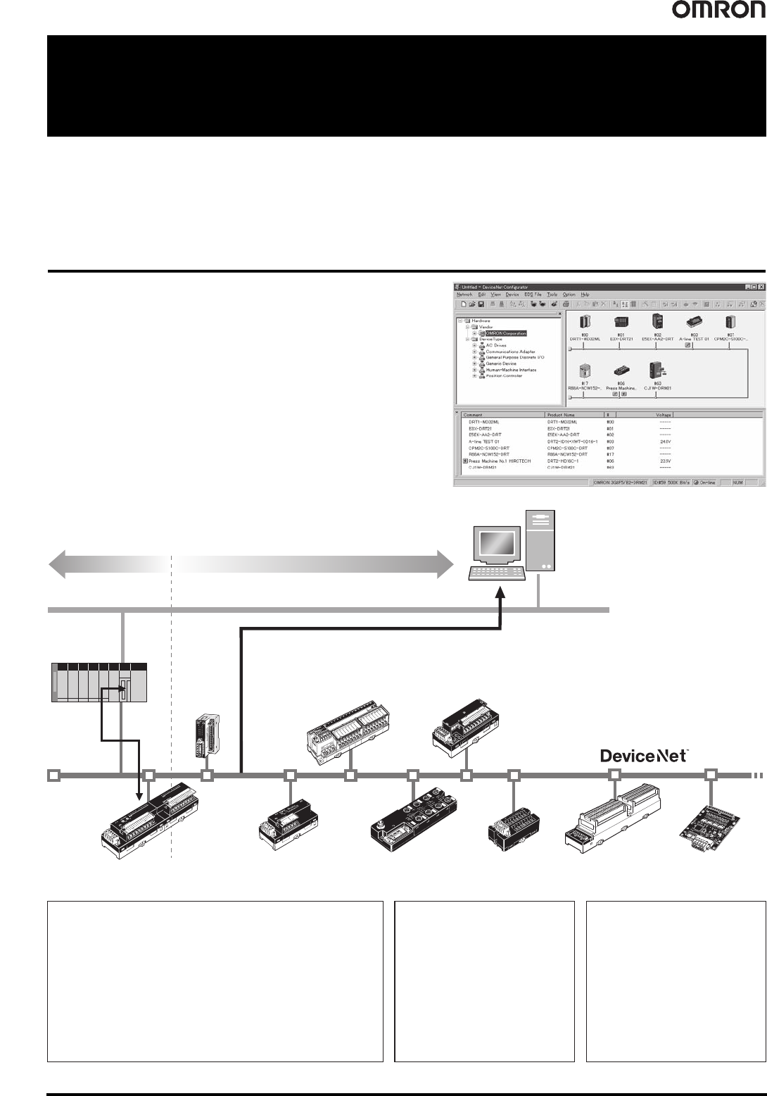
In addition to the standard control functions, the DRT2-series Smart
Slaves can collect a wide variety of manufacturing plant information and
serve as key components in maintenance and quality control systems.
DRT2-series Smart Slave Features
Improve Maintenance
• Operation time monitor function
• Contact operations counter *
• Unit conduction time monitor function
• Total ON time monitor function *
• Network power supply voltage
monitor function
• Communications error log function
• Last maintenance date
• Comparator function
• Selectable output value after error
Reduce Downtime
• Unit comments function
• Connected device comments function
• I/O power supply monitor function
• Sensor power supply short-circuit
detection function
• External load short-circuit detection
function
• Disconnected sensor detection
function
Reduce Setup Time
• Network power supply monitor
function
• Input filter function
• Power-ON inrush current
protection function
• Communications speed
auto-detect function
• Scaling function
• User compensation function
• Cumulative counter
• Moving average processing function
• Number of A/D conversion points
(conversion cycle) setting
• Peak/bottom hold function
• Top/valley hold function
• Percentage change calculation
function
* The number of contact operations monitor function and the cumulative ON time monitor function cannot be used simultaneously for the same contact.
Maintenance systemControl system Maintenance systemControl system
Maintenance information
Ethernet
PLC
Control
information
DRT2-series
Smart Slave
Remote I/O Terminals
DRT2-series
Smart Slave
Analog I/O Terminals
DRT2-series
Remote I/O Terminals
Models with 3-tier
Terminal Blocks
DRT2-series
Remote I/O Terminals
Relay Output Terminals
DRT2-series
Screw-less Clamp Terminals
Smart Slave:
DRT2-series
Board Terminals
with MIL Connectors
DRT2-series
Smart Slave
Environment-resistive Terminals
DRT2-series
Smart Slave
Sensor Terminals
● Network power supply voltage monitor
● Unit/Connected device comments
● Unit power-ON time monitor
■ Common Smart Slave Functions
DeviceNet
Configurator
DRT2-series
Smart Slave
MIL Connector
Terminals
(Transistor Model)
The DRT2-series Smart Slaves do not just handle the ON/OFF
signals of I/O devices; they can accumulate a variety of information
to improve the operating efficiency of the equipment. A maintenance
system can be constructed that is separate from the control system.
The side-by-side control system/maintenance system configuration
allows the existing DeviceNet wiring to be used, reduces the
customer’s equipment setup time, reduces the downtime in the event
of a problem, and provides preventative maintenance capabilities.
Smart Slaves DRT2 Series 11
Configurator (Ver. 2.20 or Later) Maintenance Window
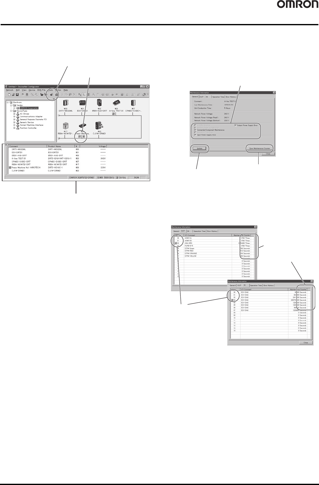
Various equipment information can be monitored from the following Configurator window (Ver. 2.20 or later) through DRT2-series Smart Slaves.
● Maintenance Mode Window
● Individual Slave’s Maintenance Information Window
A DRT2-series Smart Slave’s maintenance information window can
be displayed by double-clicking the Slave’s icon if an alarm indicator
appears next to the Slave’s icon.
Depending on the maintenance information that has been generated,
more details can be viewed by clicking the OUT tab, IN tab, or
Operation Time tab.
Maintenance information refresh icon
Reads the current maintenance information.
Alarm indicator icon
Maintenance information window
Maintenance information
Displays current maintenance information.
A Smart Slave’s maintenance counters can be
stored in flash memory. The “number of contact
operations” count is normally stored every 6
minutes, so up to 6 minutes of data may be lost
depending on when the power is turned OFF.
Refreshes the current
Slave’s maintenance
information
An alarm indicator will
appear wherever the
present value exceeds
the monitor value, so
locations requiring
maintenance can be
identified immediately.
Depending on the
maintenance information
that has been generated,
more details can be
viewed by clicking the
OUT tab, IN tab, or
Operation Time tab.
12 Smart Slaves DRT2 Series
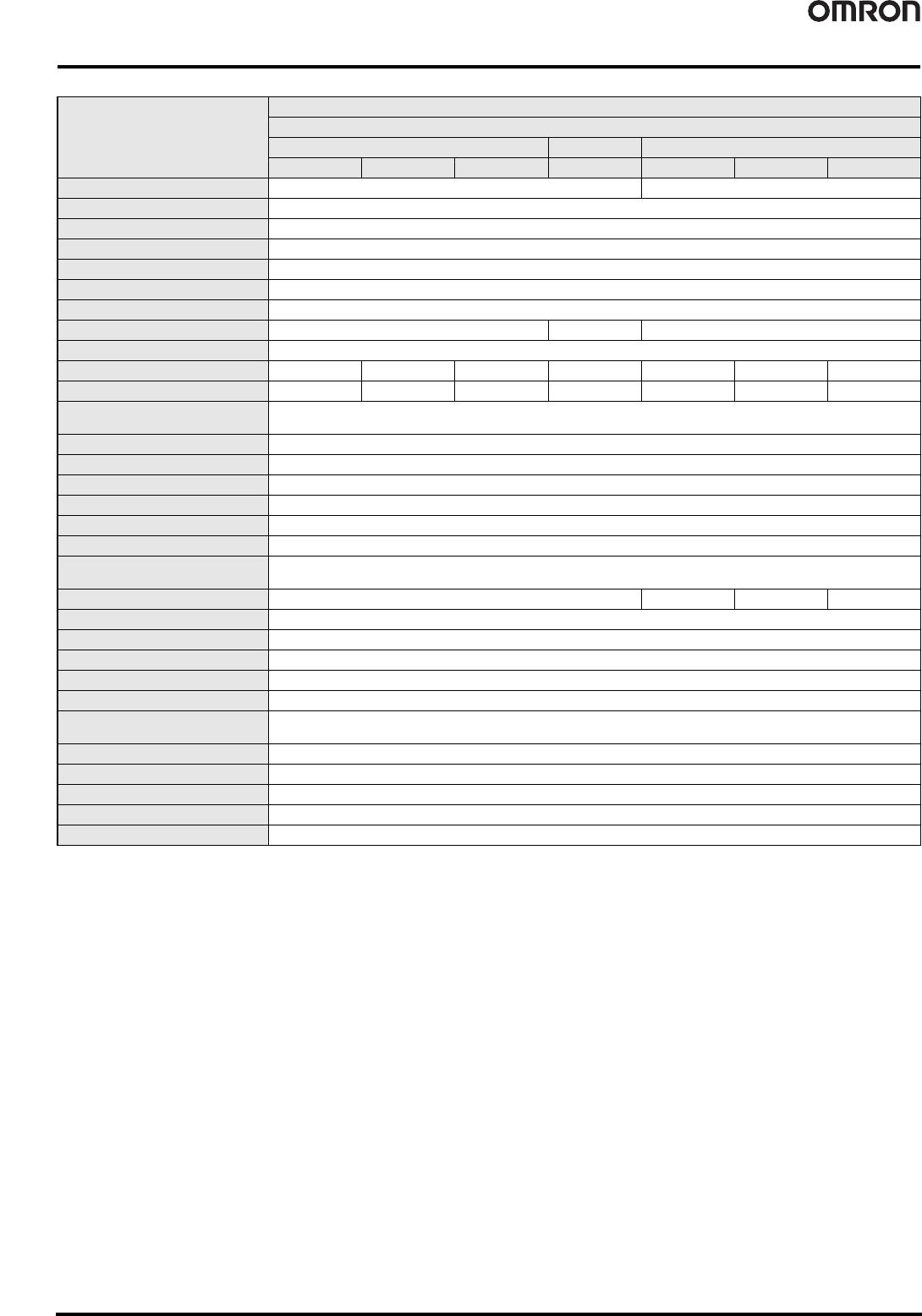
Functions Supported by Smart Slaves
OK: Function supported, ---: Function not supported.
*1. The operation time monitor cannot be used with the DRT2-@D08(-1).
*2. Expansion Units cannot be added with the DRT2-@D08(-1) or DRT2-MD16(-1).
Notice: The contact operation counter function and the total ON time monitor function cannot be used simultaneously for the same contact.
Function
General Slaves
Remote I/O Terminals
Transistors Relays Transistors with 3-tier terminal block
Input Output I/O Output Input Output I/O
Operation time monitor OK (Input+Output only) *1OK
Contact operation counter OK
Unit conduction time monitor OK
Total ON time monitor OK
Unit comments OK
Connected device comments OK
Network power supply voltage monitor OK
I/O power supply monitor OK --- OK
Communications error log monitor OK
Input filter OK --- OK --- OK --- OK
Power-ON inrush current protection OK --- OK --- OK --- OK
Sensor power supply short-circuit
detection
---
Disconnected sensor detection ---
External load short-circuit detection ---
Disconnected sensor detection ---
Removable terminal block OK
Communications speed auto-detect OK
No need to wire Unit power supply OK
No need to wire input device power
supply
---
Expansion via Expansion I/O Units OK *2 --- --- ---
Scaling ---
User compensation ---
Last maintenance date OK
Cumulative counter ---
Moving average processing ---
Number of A/D conversion points
(conversion cycle) setting
---
Peak/bottom hold ---
Top/valley hold ---
Percentage change calculation ---
Comparator ---
Selectable output value after error ---