drt2_devicenet_q102-e1_20_22_csm2147.pdf - 第122页
102 DeviceNet-compliant Digital Controllers E5AR-DRT/E5ER-DRT ● E5ER Note: Do not use the output from an Inverter for the power supply . *1. When ordering, specify the power supply. Different models are used for 100 to 2…
DeviceNet-compliant Digital Controllers E5AR-DRT/E5ER-DRT 101
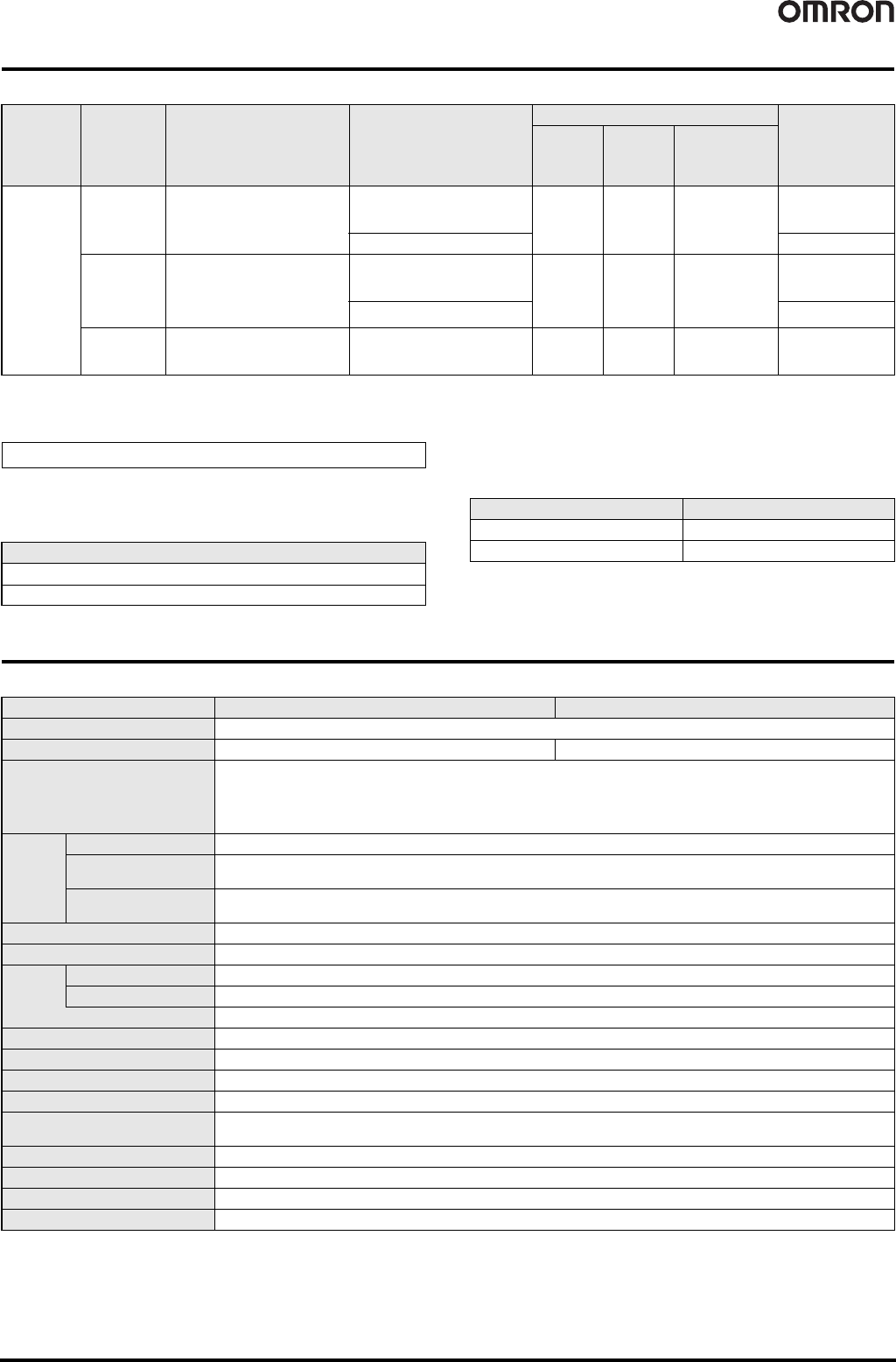
● E5ER DeviceNet-compliant Models
Note: When ordering, specify the power supply. Different models are used for 100 to 240 VAC and 24 VDC/AC.
*1. Transistor outputs.
*2. Control can be switched between closed control and floating control.
Order using the following model number together with the model
number of the Digital Controller to obtain inspection results.
Inspection Results (Sold Separately)
■ Optional Accessories (Sold separately)
● Terminal Cover
Specifications
● E5AR
Note: Do not use the output from an Inverter for the power supply.
*1. When ordering, specify the power supply. Different models are used for 100 to 240 VAC and 24 VDC/AC.
*2. Multi-input. Switch between temperature and analog input using the input type switch.
Basic insulation is provided between the power supply and input terminals and between the power supply and output terminals.
Size Type Control modes No. of outputs (control/transfer)
Optional features
Model
No. of
auxiliary
outputs
(SUB)
No. of event
inputs
Communications
48 x 96 mm
Basic Type
(1 input)
Standard control
Heating/cooling control
2
(pulse voltage + pulse voltage/
current outputs)
2 *1 2 DeviceNet
E5ER-QTB-DRT
2 (2 current outputs) E5ER-CTB-DRT
2-input Type
2-channel standard control
1-channel heating/cooling control
1-channel cascade control
1-channel control with remote SP
1-channel ratio control
2
(pulse voltage + pulse voltage/
current outputs) 2 *1 None DeviceNet
E5ER-QTW-DRT
2 (2 current outputs) E5ER-CTW-DRT
Control Valve
Control Type
(1 input)
1-channel position proportional
control *2
Relay outputs
(1 open and 1 closed)
2 *1 None DeviceNet E5ER-PRTF-DRT
Inspection Results
Model
E5AR-K
E5ER-K
Digital Controller Model
E5AR E53-COV14
E5ER E53-COV15
Item *1 Power supply voltage 100 to 240 VAC, 50/60 Hz 24 VAC, 50/60 Hz or 24 VDC
Allowed voltage variance range 85% to 110% of power supply voltage
Power consumption 22 VA max. (under maximum load) 15 VA/10 W max. (under maximum load)
Sensor input *2
Thermocouples: K, J, T, E, L, U, N, R, S, B, W
Platinum resistance temperature input sensors: Pt100
Current inputs: 4 to 20 mA DC, 0 to 20 mA DC (including remote SP input)
Voltage inputs: 1 to 5 VDC, 0 to 5 VDC, 0 to 10 VDC (including remote SP input)
(Input impedance: 150 using current input, approx. 1 M using voltage input)
Control
output
Voltage (pulse) output 12 V DC, 40 mA max., with short-circuit protection circuit
Current output
0 to 20 mA DC/4 to 20 mA DC, 500 load max. (including transfer output)
(Resolution: Approx. 54,000 at 0 to 20 mA DC, approx. 43,000 at 4 to 20 mA DC)
Relay output
Position proportional control type (open, closed)
NO-SPST 250 VAC 1 A (including inrush current)
Auxiliary output NO-SPST 250 V AC 1 A (resistive load)
Potentiometer input 100 to 2.5 k
Event
input
Contact Input ON: 1 k max., OFF: 100 k max.
Non-contact Input ON: Residual voltage 1.5 V max., OFF: Leakage current 0.1 mA max.
Short-circuit current: Approx. 4 mA
Remote SP input See Sensor inputs.
Transfer output See Control outputs.
Control method Advanced PID or ON/OFF
Setting method Digital setting by front panel keys, setting by serial communications
Indication method
7-segment digital display and LED indicators
Character heights: PV 12.8 mm, SV 7.7 mm, MV 7.7 mm
Other functions Varies by model
Ambient operating temperature -10°C to 55°C (no condensation or icing), 3 year warranty: -10°C to 55°C (no condensation or icing)
Ambient operating humidity 25% to 85%
Storage temperature -25°C to 65°C (no condensation or icing)
102 DeviceNet-compliant Digital Controllers E5AR-DRT/E5ER-DRT
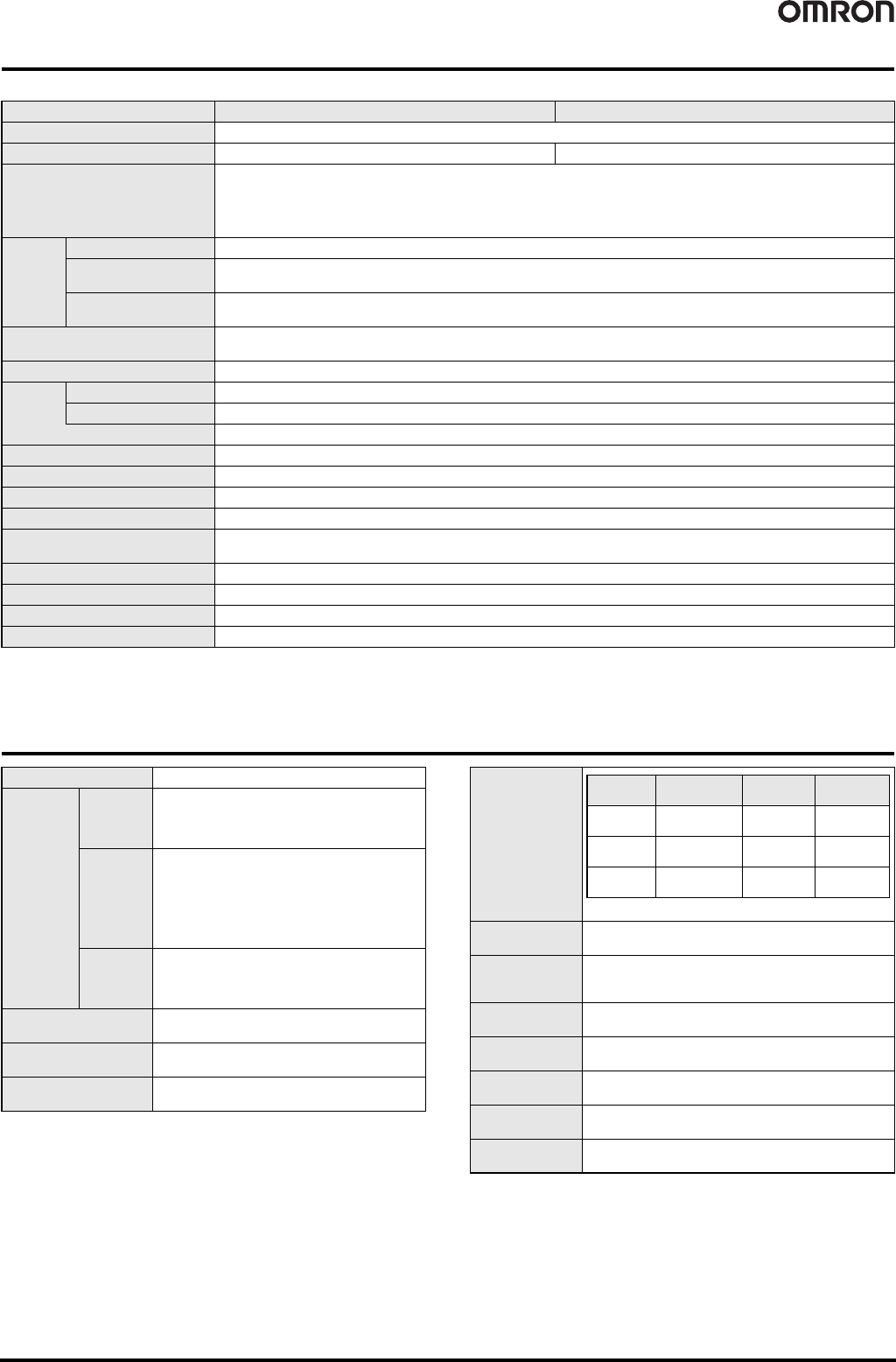
● E5ER
Note: Do not use the output from an Inverter for the power supply.
*1. When ordering, specify the power supply. Different models are used for 100 to 240 VAC and 24 VDC/AC.
*2. Multi-input. Switch between temperature and analog input using the input type switch.
Basic insulation is provided between the power supply and input terminals and between the power supply and output terminals.
DeviceNet Communications Specifications
Item *1 Power supply voltage 100 to 240 VAC, 50/60 Hz 24 VAC, 50/60 Hz or 24 VDC
Allowed voltage variance range 85% to 110% of power supply voltage
Power consumption 17 VA max. (under maximum load) 11 VA/7 W max. (under maximum load)
Sensor input *2
Thermocouples: K, J, T, E, L, U, N, R, S, B, W
Platinum resistance temperature input sensors: Pt100
Current inputs: 4 to 20 mA DC, 0 to 20 mA DC (including remote SP input)
Voltage inputs: 1 to 5 VDC, 0 to 5 VDC, 0 to 10 VDC (including remote SP input)
(Input impedance: 150 using current input, approx. 1 M using voltage input)
Control
output
Voltage (pulse) output 12 V DC, 40 mA max., with short-circuit protection circuit
Current output
0 to 20 mA DC/4 to 20 mA DC, 500 load max. (including transfer output)
(Resolution: Approx. 54,000 at 0 to 20 mA DC, approx. 43,000 at 4 to 20 mA DC)
Relay output
Position proportional control type (open, closed)
NO-SPST 250 VAC 1 A (including inrush current)
Auxiliary output
Transistor outputs, Maximum load voltage: 30 VDC, maximum load current: 50 mA
Residual voltage: 1.5 V max., leakage current: 0.4 mA max.
Potentiometer input 100 to 2.5 k
Event
input
Contact Input ON: 1 k max., OFF: 100 k max.
Non-contact Input ON: Residual voltage 1.5 V max., OFF: Leakage current 0.1 mA max.
Short-circuit current: Approx. 4 mA
Remote SP input See Sensor inputs.
Transfer output See Control outputs.
Control method Control method Advanced PID or ON/OFF
Setting method Digital setting by front panel keys, setting by communications
Indication method
7-segment digital display and LED indicators
Character heights: PV 9.5 mm, SV 7.2 mm, MV 7.2 mm
Other functions Varies by model
Ambient operating temperature -10°C to 55°C (no condensation or icing), 3 year warranty: -10°C to 50°C (no condensation or icing)
Ambient operating humidity 25% to 85%
Storage temperature -25°C to 65°C (no condensation or icing)
Communications protocol Conforms to DeviceNet
Communi-
cations
functions
Remote I/O
communi-
cations
• Master-Slave connection (polling, bit-strobe,
COS, cyclic)
• Conforms to DeviceNet communications
standards.
I/O
allocations
• Allocate any I/O data using the Configurator.
• Allocate any data, such parameters specific to the
DeviceNet and the Digital Indicator variable area.
• Input area: 2 blocks, 100 words max.
• Output area: 1 block, 100 words max.
(The first word in the area is always allocated for
the Output Execution Enabled Flags.)
Message
Communi-
cations
function
• Explicit message communications
• CompoWay/F communications commands can be
sent (commands are sent as explicit messages).
Connection form
Combination of multi-drop method and T-branch
connections (for trunk and drop lines)
Baud rate
DeviceNet: 500, 250, or 125 kbps (automatic
follow-up)
Communications media
Special 5-wire cable (2 signal lines, 2 power supply
lines, 1 shield line)
Communications
distance
The values in parentheses are for Thin Cable.
Power supply
voltage
DeviceNet power supply: 24 VDC (internal circuit)
Allowable power
supply voltage
range
DeviceNet power supply: 11 to 25 VDC
Current
consumption
50 mA max. (24 VDC)
Maximum number
of nodes
64 (DeviceNet Configurator is counted as one node when
connected)
Maximum number
of slaves
63
Error control
checks
CRC errors
DeviceNet power
supply
Supplied from DeviceNet communications connector
Baud rate
Network length
(max.)
Branch line
length
Total branch
line length
500 kbps
100 m max.
(100 m max.)
6 m max. 39 m max.
250 kbps
250 m max.
(100 m max.)
6 m max. 78 m max.
125 kbps
500 m max.
(100 m max.)
6 m max. 156 m max.
DeviceNet-compliant Digital Controllers E5AR-DRT/E5ER-DRT 103
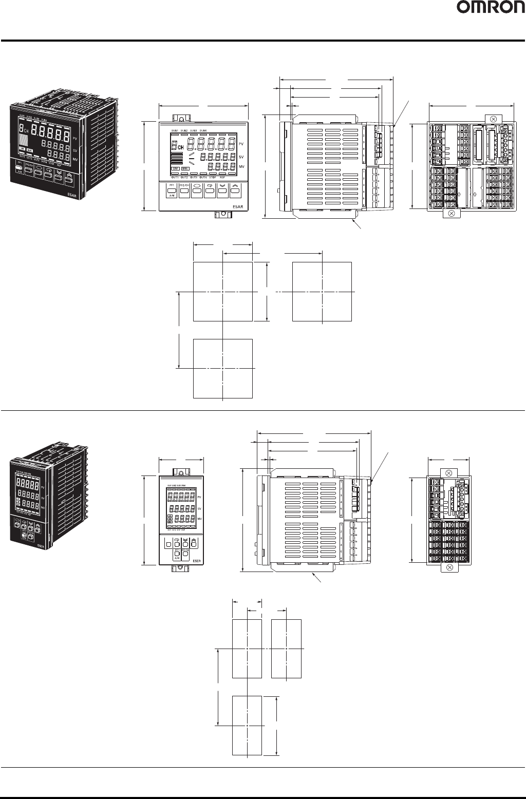
Dimensions (Unit: mm)
■ Digital Controllers
E5AR
E5ER
120 min.
92
+0.8
0
92
+0.8
0
110 min.
111
Crimp terminal size: M3
Mounting Bracket (Accessory)
95
Terminal Cover (Sold separately: E53-COV14)
96
96
2
(121.5)
11.5
99
91
91
• Mounting panel thickness: 1 to 8 mm
• Do not mount Controllers side-to-side. Maintain the installation
interval.
• Do not allow the rated ambient temperature to be exceeded
when mounting more than one Controller.
Panel Cutout Dimensions
Terminal Cover
(Sold separately: E53-COV15)
120 min.
45
+0.6
0
92
+0.8
0
Terminal Cover (Sold separately: E53-COV15)
60 min.
96
48
111
95
2
(121.5)
11.5
99
91
44
Mounting Bracket (Accessory)
• Mounting panel thickness: 1 to 8 mm
• Do not mount Controllers side-to-side. Maintain the installation
interval.
• Do not allow the rated ambient temperature to be exceeded
when mounting more than one Controller.
Panel Cutout Dimensions