drt2_devicenet_q102-e1_20_22_csm2147.pdf - 第117页
DeviceNet-compliant Digital Indicators K3HB- @ -DRT 97 Ratings ● K3HB-X/V/H/S * DeviceNet only. Power supply voltage 100 to 240 V AC Models 100 to 240 V AC (50/60 Hz) DeviceNet pow er supply: 24 VDC Allowable power suppl…
96 DeviceNet-compliant Digital Indicators K3HB-@-DRT
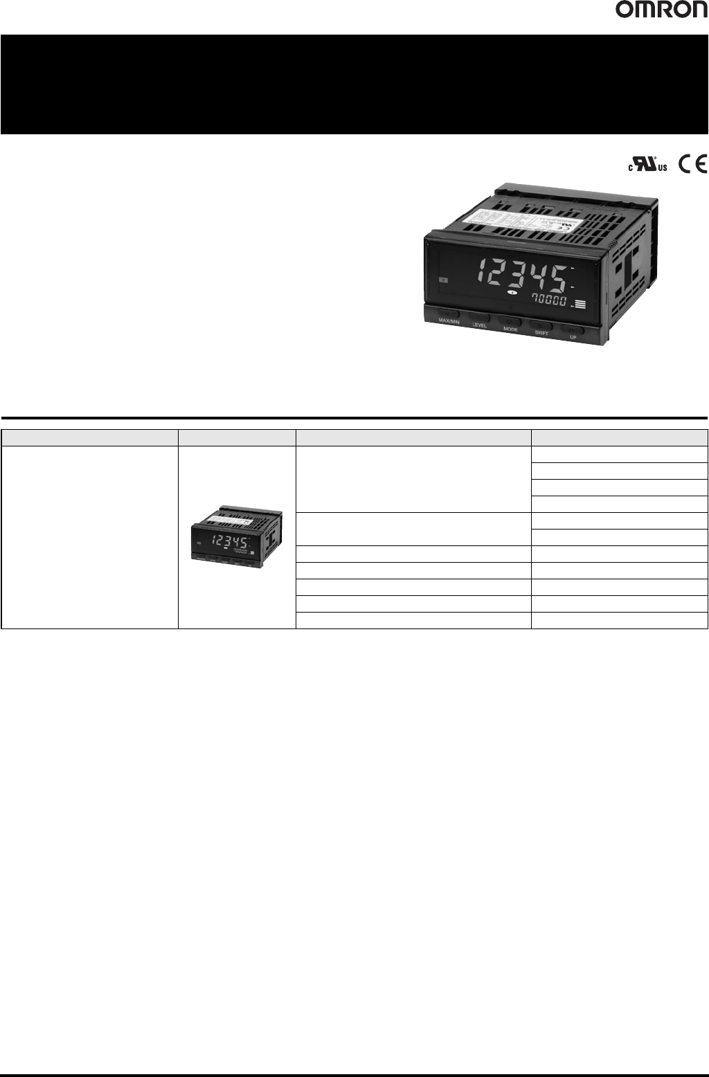
DeviceNet-compliant Digital Indicators
K3HB-@-DRT
Digital Indicators Ideal for
Measurement Displays and
Judgment of Analog Levels, Such as
Voltage Signals, Current Signals, and
Temperatures
• High-precision, high-speed sampling.
• Measurement resolution of 0.01°C and sampling of 50 times per second.
• High-visibility negative-transmissive LCD with bright backlight.
• Present values and deviations are displayed using a bar graph.
• Compliant with CE and UL standards as well as RoHS.
Ordering Information
Name Appearance Specifications Model
DeviceNet-compliant Digital Indicators
Process Indicator
K3HB-XVD-A-DRT1
K3HB-XAD-A-DRT1
K3HB-XVA-DRT1
K3HB-XAA-DRT1
Weighing Indicator
K3HB-VLC-B-DRT1
K3HB-VLC-E-DRT1
Temperature Indicator K3HB-HTA-DRT1
Linear Sensor Indicators K3HB-SSD-A-DRT1
Rotary Pulse Indicator K3HB-RNB-A-DRT1
Timer Interval Indicator K3HB-PNB-A-DRT1
Up/Down Counting Pulse Indicator K3HB-CNB-A-DRT1
DeviceNet-compliant Digital Indicators K3HB-@-DRT 97
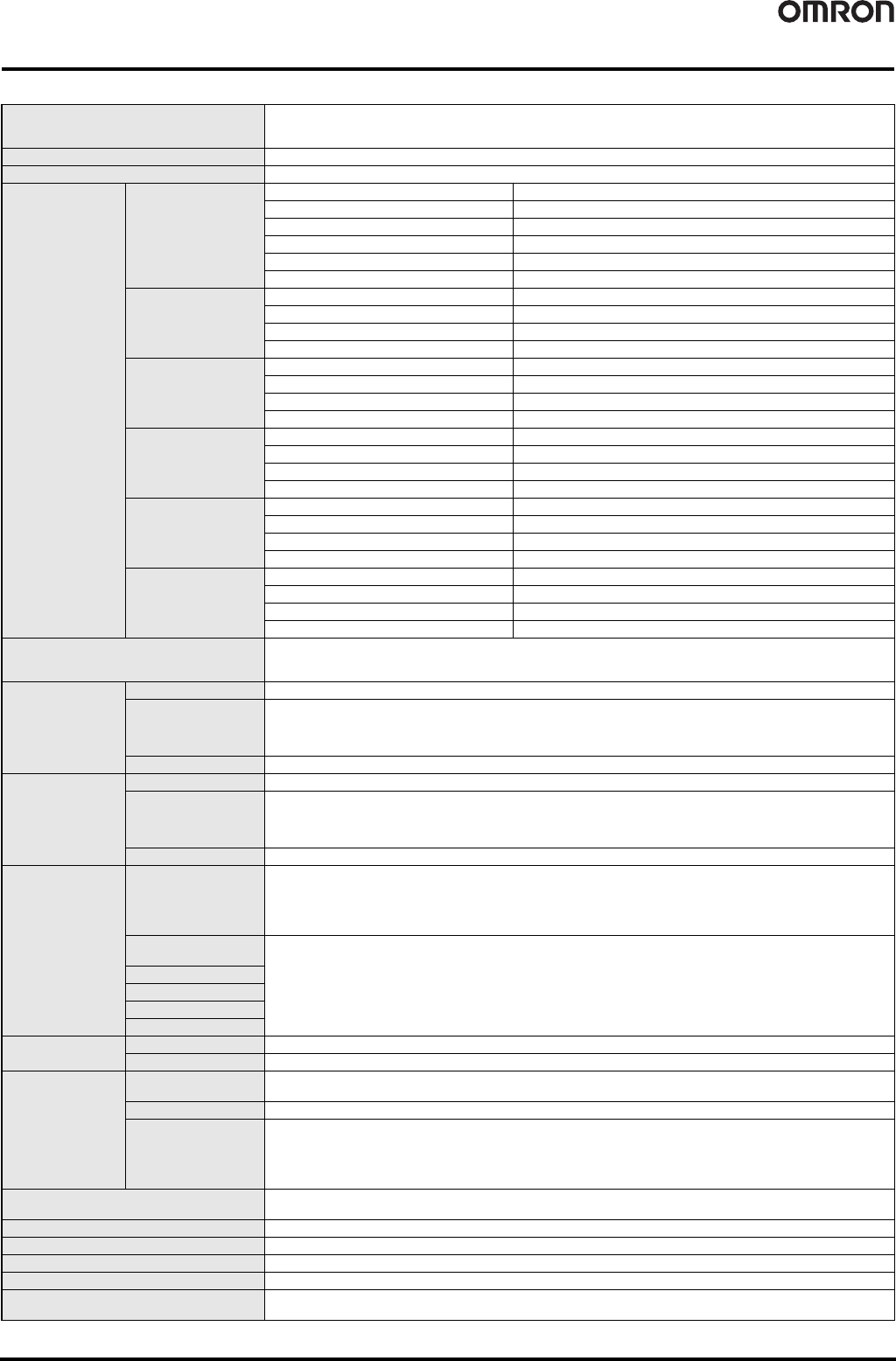
Ratings
● K3HB-X/V/H/S
* DeviceNet only.
Power supply voltage
100 to 240 VAC Models
100 to 240 VAC (50/60 Hz)
DeviceNet power supply: 24 VDC
Allowable power supply voltage range 85% to 110% of the rated power supply voltage
Power consumption 100 to 240 VAC Models: 18 VA max., 24 VAC/VDC Models: 11 VA, 7 W max.
Absolute maximum
rated input
S Model
0 to 5V ±10V
1 to 5V ±10V
±5 V ±10V
±10 V ±14.5V
0 to 20 mA 31 mA
4 to 20 mA 31 mA
XVD Model
±199.99 V Allowable instantaneous overload (30 s): ±400 V
±19.999 V Allowable instantaneous overload (30 s): ±200 V
±1.9999 V Allowable instantaneous overload (30 s): ±200 V
1.0000 to 5.0000V Allowable instantaneous overload (30 s): ±200 V
XVA Model
0.0 to 400.0 V Allowable instantaneous overload (30 s): 700 V
0.00 to 199.99 V Allowable instantaneous overload (30 s): 700 V
0.000 to 19.999 V Allowable instantaneous overload (30 s): 400 V
0.0000 to 1.9999 V Allowable instantaneous overload (30 s): 400 V
XAD Model
±199.99 mA Allowable instantaneous overload (30 s): ±400 V
±19.999 mA Allowable instantaneous overload (30 s): ±200 V
±1.9999 mA Allowable instantaneous overload (30 s): ±200 V
4.000 to 20.000 mA Allowable instantaneous overload (30 s): ±200 V
XAA Model
0.000 to 10.000 A Allowable instantaneous overload (30 s): 20 A
0.0000 to 1.9999 A Allowable instantaneous overload (30 s): 20 A
0.00 to 199.99 mA Allowable instantaneous overload (30 s): 2 A
0.000 to 19.999 mA Allowable instantaneous overload (30 s): 2 A
V Model
0.00 to 199.99 mV Allowable instantaneous overload (30 s): ±200 V
0.000 to 19.999 mV Allowable instantaneous overload (30 s): ±200 V
±100.00 mV Allowable instantaneous overload (30 s): ±200 V
±199.99 mV Allowable instantaneous overload (30 s): ±200 V
External power supply
12 VDC ±10%, 80 mA (only for models with external power supplies)
10 VDC ±5%, 100 mA (only for models with external power supplies)
5 VDC ±5%, 100 mA (only for models with external power supplies)
Input range
(measurement
range)
S Model DC voltages or currents (0 to 20 mA, 4 to 20 mA, 0 to 5 V, 1 to 5 V, ±5 V, ±10 V), 2 channels
X Model
(measurement category
II)
DC voltage: ±199.99 V, ±19.999 V, ±1.999 V, 1.000 to 5.000 V
DC current: ±199.99 mA, ±19.999 mA, ±1.999 mA, 4.000 to 20.000 mA
AC voltage: 0.0 to 400.0 V, 0.00 to 199.99 V, 0.000 to 19.999 V, 0.000 to 1.9999 V
AC current: 0.000 to 10.000 A, 0.0000 to 1.9999 A, 0.00 to 199.99 mA, 0.000 to 19.999 mA
V Model Load cell: 0.00 to 199.99 mV, 0.000 to 19.999 mV, ±100.00 mV, ±199.99 mV
Input impedance
S Model Current range: 120 max., Voltage range: 1 M max.
X Model
DC voltage (±199.99 V): 10 M min./DC voltage (other ranges): 1 M min.
DC current (±199.99 mA): 1 max./(±19.999 mA and 4 to 20 mA): 10 max./(±1.9999 mA): 33 max.
AC voltage: 1 M min., DC current (0 to 10 A and 0 to 1.9999 A): 0.5 VAC/(0 to 199.99 mA): 1 max./(0 to 19.999 mA):
10 max.
V Model Load cell: 1 M min.
Event inputs
Timing input
NPN open collector or no-voltage contact signal
ON residual voltage: 3 V max.
ON current at 0 : 17 mA max.
Max. applied voltage: 30 VDC max.
OFF leakage current: 1.5 mA max.
Startup compensation
timer input
NPN open collector or no-voltage contact signal
ON residual voltage: 2 V max.
ON current at 0 : 4 mA max.
Max. applied voltage: 30 VDC max.
OFF leakage current: 0.1 mA max.
Hold input
Reset input
Forced-zero input
Bank input
A/D conversion
method
S Model Sequential comparison system
H/X/V Model Digital-sigma method
Output ratings
Relay output
250 VAC, 30 VDC, 5 A (resistive load)
Mechanical life expectancy: 5,000,000 operations, Electrical life expectancy: 100,000 operations
Transistor output Maximum load voltage: 24 VDC, Maximum load current: 50 mA, Leakage current: 100 µA max.
Linear output
Linear output 0 to 20 mA DC, 4 to 20 mA:
Load: 500 max, Resolution: Approx. 10,000, Output error: ±0.5% FS
Linear output 0 to 5 VDC, 1 to 5 VDC, 0 to 10 VDC:
Load: 5 k max, Resolution: Approx. 10,000, Output error: ±0.5% FS
(1 V or less: ±0.15 V; not output for 0 V or less)
Display method
Negative LCD (backlit LED) display, 7-segment digital display (character heights: PV: 14.2 mm (switches between green and
red), SV: 4.9 mm (green))
Ambient operating temperature -10°C to 55°C (with no icing or condensation)
Ambient operating humidity 25% to 85%
Storage temperature -25°C to 65°C (with no icing or condensation)
Altitude 2,000 m max.
Accessories
2 fixtures, unit stickers, instruction manual. watertight packing, terminal cover, DeviceNet connector * and crimp terminals
(Hirose HR31-SC-121) *
98 DeviceNet-compliant Digital Indicators K3HB-@-DRT
● K3HB-R/P/C
*1. DC power supply models require a control power supply capacity of approximately 1 A per Unit when power is turned ON. Particular attention is required when using two or
more DC power supply models. The OMRON S8VS-series DC Power Supply Unit is recommended.
*2. PNP input types are also available.
*3. For K3HB-series DeviceNet models, use only the DeviceNet Connector included with the product. The crimp terminals provided are for Thin Cables.
*4. Depends on the model.
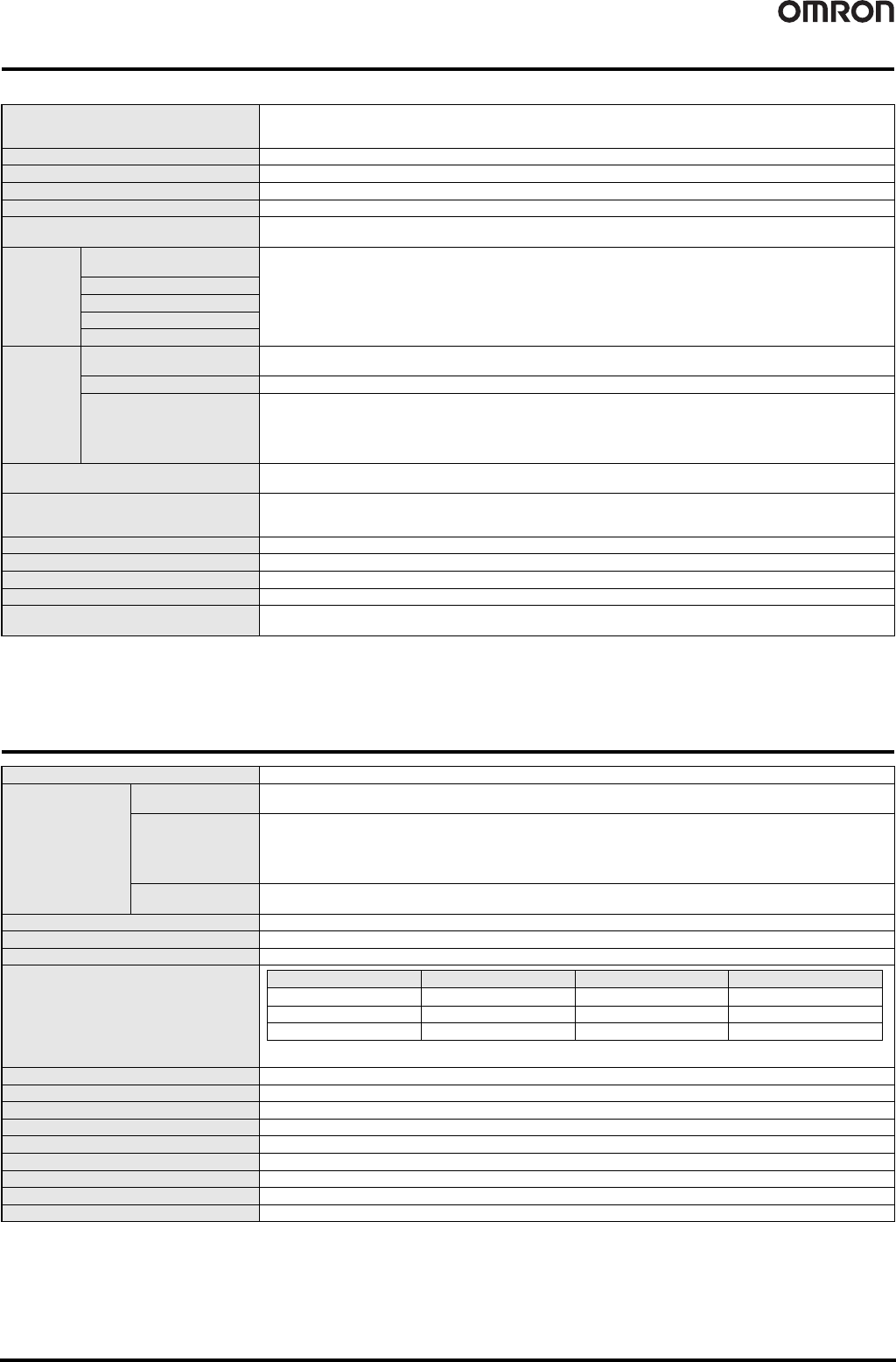
DeviceNet Communications Specifications
Power supply voltage
100 to 240 VAC Models
24 VAC/VDC Models
DeviceNet power supply: 24 VDC
Allowable power supply voltage range 85% to 110% of the rated power supply voltage, DeviceNet power supply: 11 to 25 VDC
Power consumption (under maximum load) *1 100 to 240 VAC: 18 VA max., 24 VAC/VDC: 11 VA/7 W max.
Current consumption DeviceNet power supply: 50 mA max. (24 VDC)
Inputs No-voltage contact, voltage pulse, and open collector
External power supply
12 VDC ±10%, 80 mA (only for models with external power supplies)
10 VDC ±5%, 100 mA (only for models with external power supplies)
Event inputs
*2, *4
Startup compensation timer
input
NPN open collector or no-voltage contact signal
ON residual voltage: 2 V max.
ON current at 0 : 4 mA max.
Max. applied voltage: 30 VDC max.
OFF leakage current: 0.15 mA max.
Hold input
Reset input
Compensation input
Bank input
Outputs *4
Relay output
250 VAC, 30 VDC, 5 A (resistive load)
Mechanical life expectancy: 5,000,000 operations, Electrical life expectancy: 100,000 operations
Transistor output Maximum load voltage: 24 VDC, Maximum load current: 50 mA, Leakage current: 100 µA max.
Linear output
Linear output 0 to 20 mA DC, 4 to 20 mA:
Load: 500 max, Resolution: Approx. 10,000, Output error: ±0.5% FS
Linear output 0 to 5 VDC, 1 to 5 VDC, 0 to 10 VDC:
Load: 5 k max, Resolution: Approx. 10,000, Output error: ±0.5% FS
(1 V or less: ±0.15 V; not output for 0 V or less)
Display method
Negative LCD (backlit LED) display, 7-segment digital display (character heights: PV: 14.2 mm (switches between green
and red), SV: 4.9 mm (green))
Main functions *4
Scaling, measurement operation selection, averaging, previous average value comparison, output hysteresis, output ON
delay, output test, teaching, display selection, display color switching, key protection, bank selection, display refresh period,
maximum/minimum hold, and reset
Ambient operating temperature -10°C to 55°C (with no icing or condensation)
Ambient operating humidity 25% to 85%
Storage temperature -25°C to 65°C (with no icing or condensation)
Altitude 2,000 m max.
Accessories
Watertight packing, 2 fixtures, terminal cover, unit stickers, instruction manual. DeviceNet models also include a
DeviceNet connector (Hirose HR31-5.08P-5SC(01)) and crimp terminals (Hirose HR31-SC-121) *3
Communications protocol Conforms to DeviceNet
Supported
communications
Remote I/O
communications
• Master-Slave connection (polling, bit-strobe, COS, cyclic)
• Conforms to DeviceNet communications standards.
I/O allocations
• Allocate any I/O data using the Configurator.
• Allocate any data, such as DeviceNet-specific parameters and variable area for Digital Indicators.
• Input area: 2 blocks, 100 words max.
• Output area: 1 block, 100 words max. (The first word in the area is always allocated for the Output Execution Enabled
Flags.)
Message
communications
• Explicit message communications
• CompoWay/F communications commands can be executed (using explicit message communications)
Connection form Combination of multi-drop method and T-branch connections (for trunk and drop lines)
Baud rate DeviceNet: 500, 250, or 125 kbps (automatic follow-up)
Communications media Special 5-wire cable (2 signal lines, 2 power supply lines, 1 shield line)
Communications distance
The values in parentheses are for Thin Cable.
Power supply voltage 24-VDC DeviceNet power supply
Allowable power supply voltage range 11 to 25-VDC DeviceNet power supply
Current consumption 50 mA max. (24 VDC)
Maximum number of nodes 64 (DeviceNet Configurator is counted as one node when connected)
Maximum number of slaves 63
Error control checks CRC errors
DeviceNet power supply Supplied from DeviceNet communications connector
Current consumption 50 mA max. (24 VDC)
Maximum I/O points Maximum number of slaves: 63
Baud rate Network length (max.) Branch line length Total branch line length
500 kbps 100 m max. (100 m max.) 6 m max. 39 m max.
250 kbps 250 m max. (100 m max.) 6 m max. 78 m max.
125 kbps 500 m max. (100 m max.) 6 m max. 156 m max.