drt2_devicenet_q102-e1_20_22_csm2147.pdf - 第144页
124 Safe ty I/O Terminals DST1 Series Dimensions (Unit: mm) DST1-MRD08SL-1 Safety Precautions ● Be sure to read the following operation manual f or precauti ons and other details required for correct use of the Safety Ne…
Safety I/O Terminals DST1 Series 123
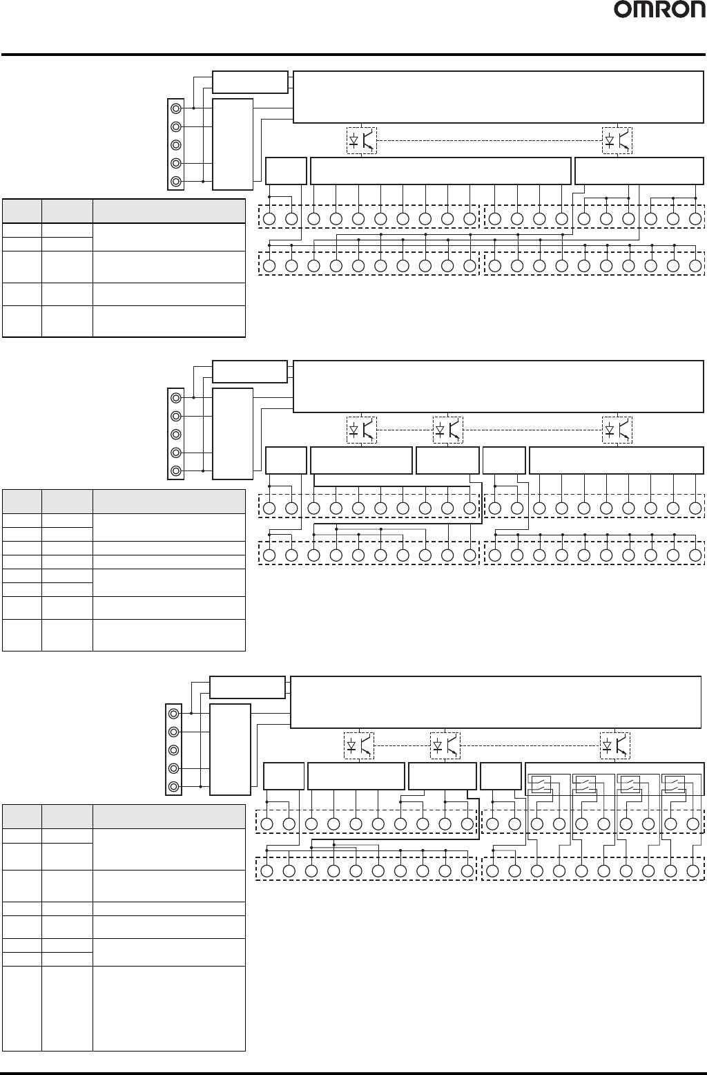
Internal Circuit Diagrams
V+
CAN H
DRAIN
CAN L
V-
G G T0 T1 T0 T1 T0 T1 T0 T1 T0 T1 T0 T1 G G G G G G
11 12 13 14 15 16 17 18 19 20 31 32 33 34 35 36 37 38 39 40
V
Safety Input Circuit
(Sink input)
Test Output Circuit
(Source output)
V
IN0 IN1 IN2 IN3 IN4 IN5 IN6 IN7 IN8 IN9
IN10 IN11
T2 T2 T2 T3 T3 T3
12345678 910 2122232425262728 29 30
DeviceNet
Physical
Layer
Input Power
Supply
Circuit
DC-DC Converter
(Non-insulated)
Internal Circuits
Terminal
No.
Name Functions
1, 2 V
Power supply terminal (24 VDC) for input
device and test output
11, 12 G
35 to 40 G
Common terminal
(Terminal No. 11, 12 and 35 to 40 are
internally connected.)
3 to 10
21 to 24
IN0 to IN11 Safety input terminal
13 to 20
25 to 30
31 to 34
T0 to T3 Test output terminal
DST1-ID12SL-1
V+
CAN H
DRAIN
CAN L
V-
G0 G0 T0 T1 T0 T1 T0 T1 T2 T3 G1 G1 G1 G1 G1 G1 G1 G1 G1 G1
11 12 13 14 15 16 17 18 19 20 31 32 33 34 35 36 37 38 39 40
V0
Safety Output Circuit
(Source output)
V0
IN0 IN1 IN2 IN3 IN4 IN5 IN6 IN7
V1 V1
OUT0 OUT1 OUT2 OUT3 OUT4 OUT5 OUT6 OUT7
1 2 3 4 5 6 7 8 9 10 21 22 23 24 25 26 27 28 29 30
DeviceNet
Physical
Layer
Input Power
Supply
Circuit
Output Power
Supply Circuit
Test Output
Circuit
(Source output)
Safety Input Circuit
(Sink input)
DC-DC Converter
(Non-insulated)
Internal Circuits
Terminal
No.
Name Functions
1, 2 V0
Power supply terminal (24 VDC) for input
device and test output
11, 12 G0
3 to 10 IN0 to IN7 Safety input terminal
13 to 20 T0 to T3 Test output terminal
21, 22 V1
Power supply terminal (24 VDC) for output
device
31, 32 G1
23 to 30
OUT0 to
OUT7
Safety output terminal
33 to 40 G1
Common terminal
(Terminal Nos. 31 to 40 are internally
connected.)
DST1-MD16SL-1
DST1-XD0808SL-1
V+
CAN H
DRAIN
CAN L
V-
G0 G0 T0 T1 T0 T1 G0 G0 G0 G0 G1 G1 C0
C0e
C1
Ry
0
Ry
1
Ry
2
Ry
3
C1e
C2
C2e
C3
C3e
11 12 13 14 15 16 17 18 19 20 31 32 33 34 35 36 37 38 39 40
V0
DeviceNet
Physical
Layer
Input Power
Supply
Circuit
Output Power
Supply Circuit
Test Output
Circuit
(Source output)
Safety Input Circuit
(Sink input)
DC-DC Converter
(Non-insulated)
V0 IN0 IN1 IN2 IN3 T2 T2 T3 T3 V1 V1
OUT0
OUT0e
OUT1
OUT1e
OUT2
OUT2e
OUT3
OUT3e
12345678 910 2122 232425262728 29 30
Internal Circuits
Terminal
No.
Name Functions
1, 2 V0 Power supply terminal (24 VDC) for input
device, test output, and monitoring the
safety relay NC contact of the internal
circuit
11, 12 G0
17 to 20 G0
Common terminal
(Terminal Nos. 11, 12 and 17 to 20 are
internally connected.)
3 to 6 IN0 to IN3 Safety input terminal
7 to 10
13 to 16
T0 to T3 Test output terminal
21, 22 V1
Power supply terminal (24 VDC) for driving
the safety relay of the internal circuit
31, 32 G1
23 to 30
33 to 40
OUT0 to
OUT3
C0 to C3
OUT0e to
OUT3e
C0e to C3e
Safety output terminal
(The outputs of terminal No. 23/33 (OUT0)
and 24/34 (OUT0e) are the same.)
(The outputs of terminal No. 25/35 (OUT1)
and 26/36 (OUT1e) are the same.)
(The outputs of terminal No. 27/37 (OUT2)
and 28/38 (OUT2e) are the same.)
(The outputs of terminal No. 29/39 (OUT3)
and 30/40 (OUT3e) are the same.)
DST1-MRD08SL-1
124 Safety I/O Terminals DST1 Series
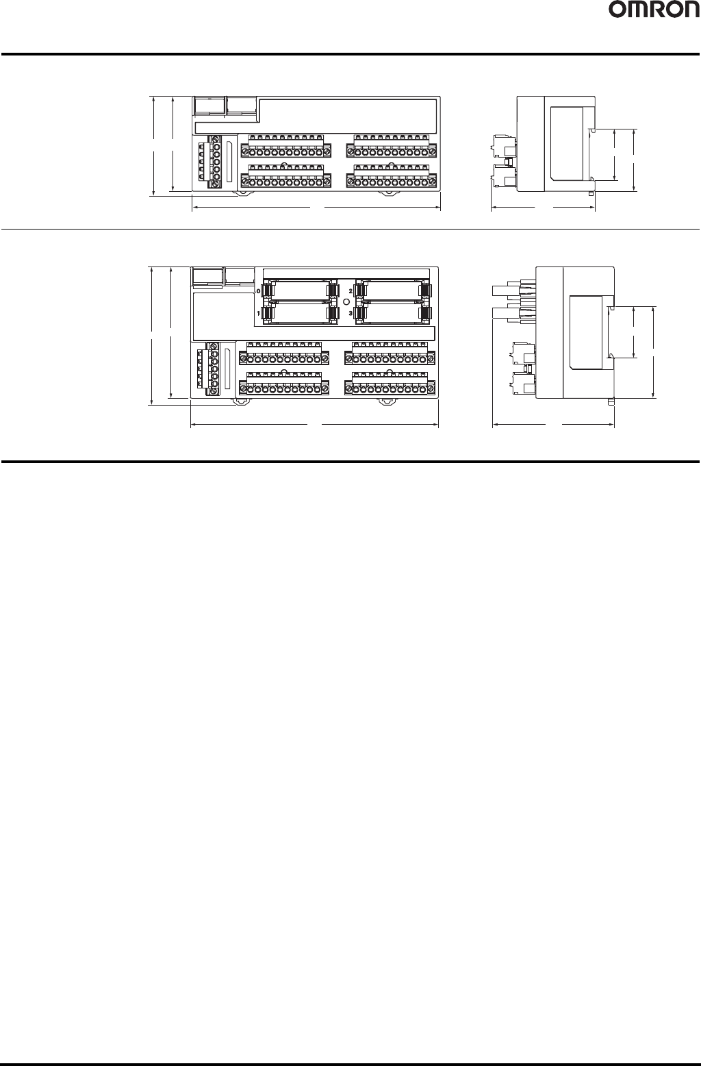
Dimensions (Unit: mm)
DST1-MRD08SL-1
Safety Precautions
● Be sure to read the following operation manual for precautions and other details required for correct use of the Safety
Network Controller. CIP Safety on DeviceNet Safety I/O Terminals Operation Manual (Cat. No. Z904)
65(68.15)
170
35.5
42.75
71.4
DST1-ID12SL-1
DST1-MD16SL-1
DST1-XD0808SL-1
90
(94.7)
170
35.5
63
83.2
Network Configurator WS02-CFSC1-E 125
Network Configurator
WS02-CFSC1-E
Programming Software for
Creating Safety Circuits.
• Performs settings for the Safety Network Controllers and Safety
I/O Terminals.
• Provides safety circuit programming functions.
• Provides monitoring functions for safety circuits.
• Includes DeviceNet Configurator functions.
Ordering Information
Note: Consult your OMRON representative for the license not listed above.
* The applicable OS depends on the version. Refer to general specifications for details.
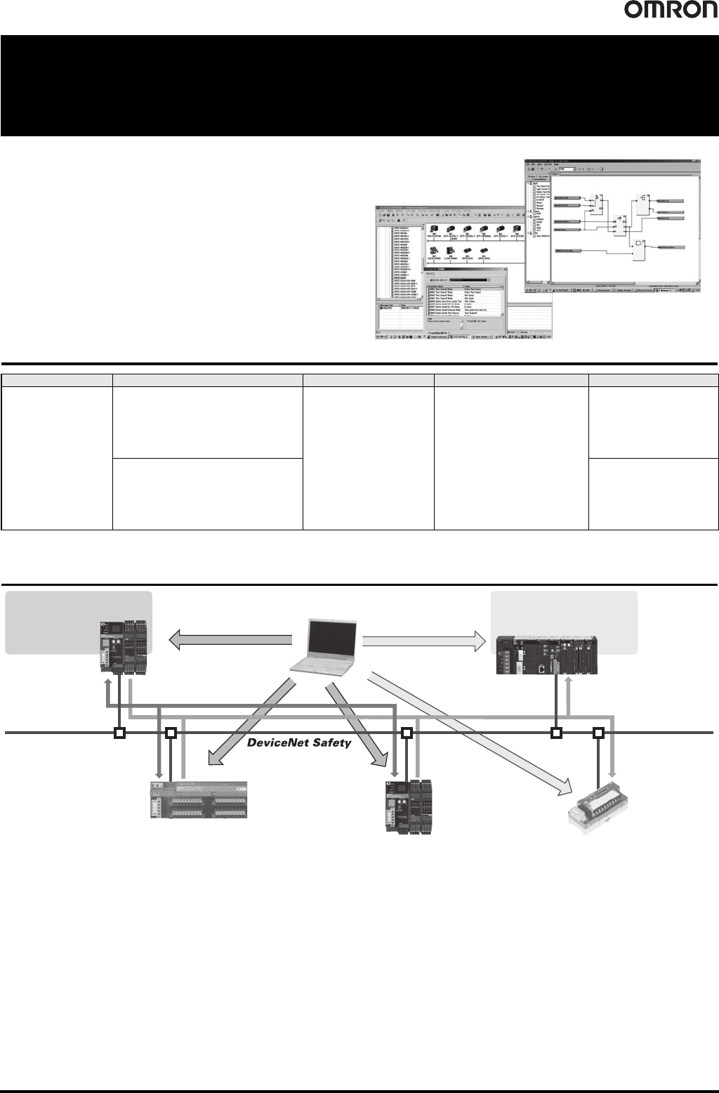
System Configuration
Name Components Applicable computer Applicable OS * Model
Network Configurator
Installation disc (CD-ROM: 1 license)
IBM PC/AT or compatible
Windows XP Service Pack 3
(32-bit edition)
Windows Vista Service Pack 2
(32-bit edition, 64-bit edition)
Windows 7
(32-bit edition, 64-bit edition)
Windows 8
(32-bit edition, 64-bit edition)
Windows 8.1
(32-bit edition, 64-bit edition)
Windows 10
(32-bit edition, 64-bit edition)
WS02-CFSC1-EV3
Upgrade disc (CD-ROM: 1 license) WS02-CFSC1-EV3-UP
Standard PLC and Master
Safety I/O Terminal
Safety Network Controller
Standard Slave
Safety Network
Controller
Network Configurator
Safety Configuration Standard configuration
Safety communications
Standard
communications
Standard Slave functionSafety Master function
Standard Slave functionSafety Slave function
Standard Slave function
Safety Slave function
Safety Control Using the Safety
Network Controller
• Safety I/O
communications
Standard PLC control and monitoring
• Standard I/O communications
• Explicit message communications