drt2_devicenet_q102-e1_20_22_csm2147.pdf - 第94页
74 Digital I/O Un its GT1- @ D16(-1)/ @ D16MX(-1)/ @ D16ML(-1)/ @ D32ML(-1)/ @ D16 Digital I/O Units GT1- @ D16(-1)/ @ D16MX(-1)/ @ D16ML(-1)/ @ D32ML(-1)/ @ D16DS(-1) Digital I/O Units Compatible with MULTIPLE I/O TERMI…
Communications Unit DRT1-COM 73
Communications Unit
DRT1-COM
Connects to a Total Maximum of Eight
Digital I/O, Analog I/O, and Relay Output
Units Compatible with MULTIPLE I/O
TERMINAL.
• Allows flexible combinations of I/O points.
• Covering a total cable length of 3 m.
• DIN track mounting.
Ordering Information
General Specifications
Specifications
* One cable is provided with each I/O Unit.
Note: The total current consumption for I/O Unit interfaces must not exceed 0.4 A.
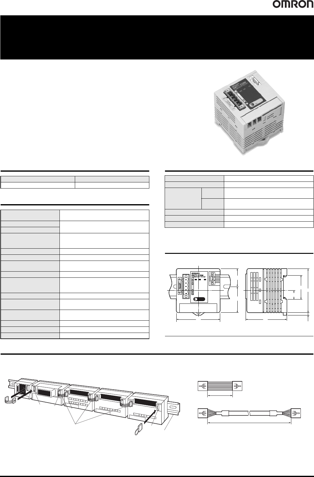
Dimensions (Unit: mm)
DRT1-COM
Mounting and Connecting Units
● Mounting to DIN Track and Connecting I/O Unit Connecting Cable
Power supply voltage Model
24 VDC DRT1-COM
Communications power
supply voltage
11 to 25 VDC (supplied from the communications
connector)
Internal power supply voltage
20.4 to 26.4 VDC
(24 VDC +10%/-15%)
I/O power supply voltage
Current consumption
Communications: 30 mA max.
Internal circuit: 0.6 A at 24 VDC
(with max. I/O load)
Dielectric strength 500 VAC
Noise immunity Conforms to IEC61000-4-4, 2 kV (Power line)
Vibration resistance
10 to 150 Hz, 1.0-mm double amplitude or
70 m/s
2
Shock resistance 200 m/s
2
Mounting strength
No damage when 100 N pull load was applied in
all directions (10 N min. in the DIN track
direction)
Terminal strength No damage when 100 N pull load was applied
Screw tightening torque
0.3 to 0.5 N
·m
Phoenix connector: 0.25 to 0.3 N
·m
Ambient operating
temperature
-10°C to 55°C (with no icing or condensation)
Ambient operating humidity 25% to 85%
Ambient storage temperature -25°C to 65°C (with no icing or condensation)
Accessories End connector (one)
Connectable Units 8
Unit I/O points 1,024 max. (including inputs and outputs)
Communications
distance
Total
extension
3 m max.
Between
Units
1 m max. (40 mm max. with the standard cable
provided with the Unit) *
Dielectric strength 500 VAC for 1 min.
Mounting method DIN 35 mm-track mounting
Unit output power supply 0.4 A max. (see Note.)
65
4
12.6
27.6
37.4
64
65
35
Note: The Unit is shown with the end connector mounted in the above diagram.
Communications
Unit
DRT1-COM
Digital I/O Unit
GT1-ID16
I/O Unit Connecting Cable
Standard cable: 40 mm
GCN1-100: 1 m
(One cable is included with
each I/O Unit.)
Same I/O Unit Connecting Cable
as at left
End connector
(One is provided with the
Communications Unit.)
DIN Track
Digital I/O Unit
GT1-OD16MX
Analog Input Unit
GT1-AD08MX
Analog Output Unit
GT1-DA04MX
(1)
(1)
(2)
(2)
Note: The connecting cable for the I/O Unit is shown below.
Accessory Cable
GCN1-100 (Sold Separately)
40 mm
1 m
74
Digital I/O Units
GT1-
@
D16(-1)/
@
D16MX(-1)/
@
D16ML(-1)/
@
D32ML(-1)/
@
D16
Digital I/O Units
GT1-
@
D16(-1)/
@
D16MX(-1)/
@
D16ML(-1)/
@
D32ML(-1)/
@
D16DS(-1)
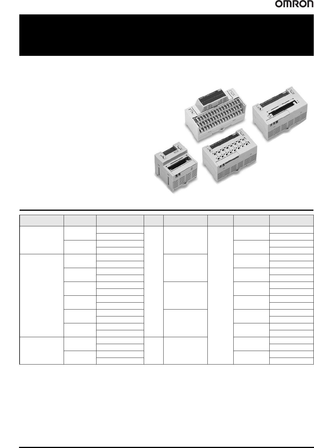
Digital I/O Units Compatible with MULTIPLE I/O TERMINAL
• Terminal block, connector, and high-density connector
models are available.
• The circuit block of the terminal block model can be
mounted or dismounted for ease of maintenance without
disconnecting the wires.
• DIN track mounting.
Ordering Information
Unit I/O classification Internal I/O common I/O points I/O connections
Power supply
voltage
I/O specification Model
Terminal block model
Digital input
NPN (+ common)
16
M3 terminal board
24 VDC
DC/transistor
GT1-ID16
PNP (- common) GT1-ID16-1
Digital output
NPN (- common)
0.5 A, DC/transistor
GT1-OD16
PNP (+ common) GT1-OD16-1
Connector model
Digital input
NPN (+ common)
Molex connector
DC/transistor
GT1-ID16MX
PNP (- common) GT1-ID16MX-1
Digital output
NPN (- common)
0.5 A, DC/transistor
GT1-OD16MX
PNP (+ common) GT1-OD16MX-1
Digital input
NPN (+ common)
Fujitsu connector
DC/transistor
GT1-ID16ML
PNP (- common) GT1-ID16ML-1
Digital output
NPN (- common)
0.5 A, DC/transistor
GT1-OD16ML
PNP (+ common) GT1-OD16ML-1
Digital input
NPN (+ common)
D-sub 25-pin connector
DC/transistor
GT1-ID16DS
PNP (- common) GT1-ID16DS-1
Digital output
NPN (- common)
0.5 A, DC/transistor
GT1-OD16DS
PNP (+ common) GT1-OD16DS-1
High-density connector
model
Digital input
NPN (+ common)
32 Fujitsu connector
DC/transistor
GT1-ID32ML
PNP (- common) GT1-ID32ML-1
Digital output
NPN (- common)
0.5 A, DC/transistor
GT1-OD32ML
PNP (+ common) GT1-OD32ML-1
Digital I/O Units
GT1-
@
D16(-1)/
@
D16MX(-1)/
@
D16ML(-1)/
@
D32ML(-1)/
@
D16
75
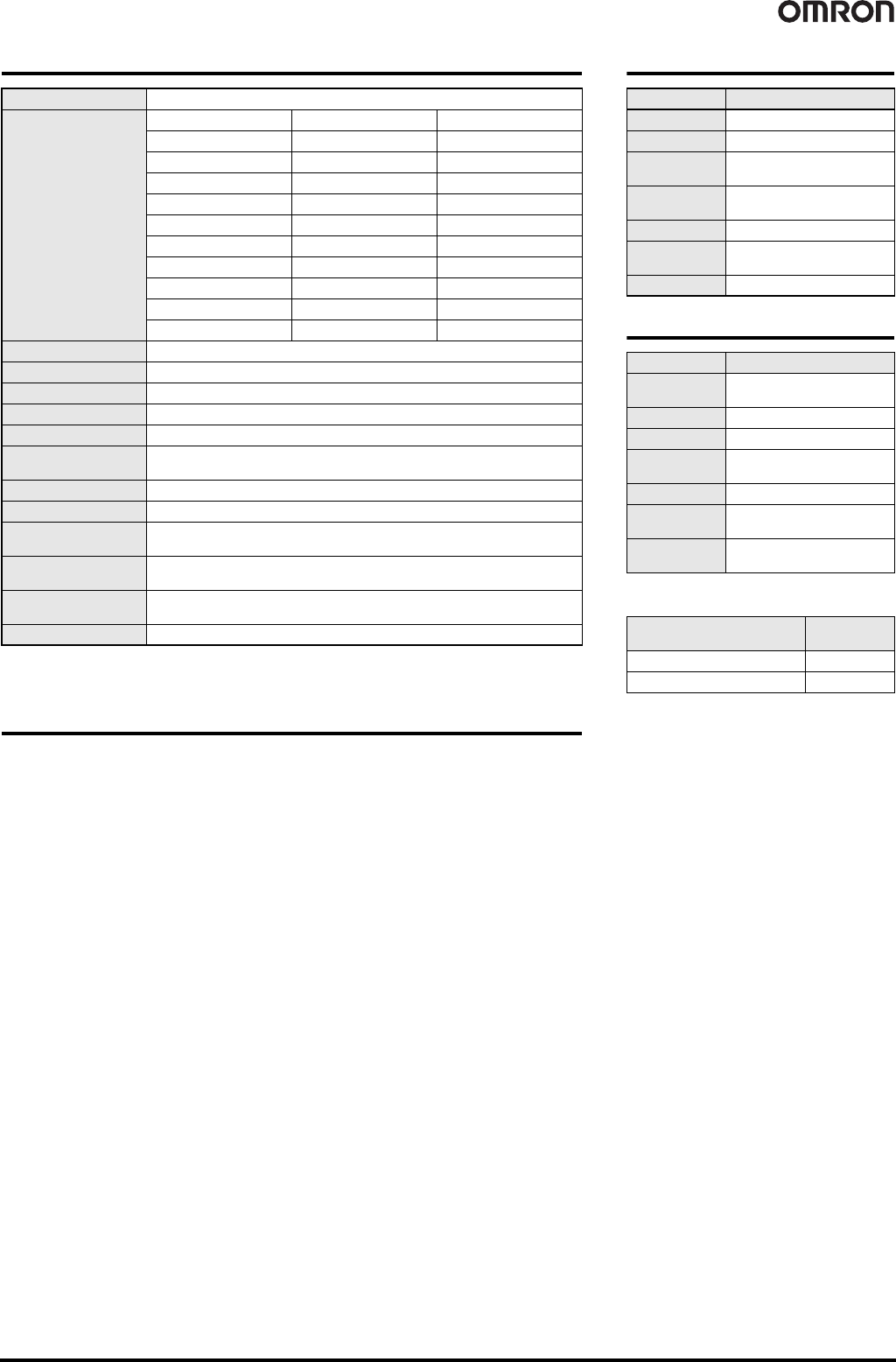
General Specifications
* The above current consumption is a value with all 16 and 32 points turned ON excluding the current consumption
of the external sensor connected to the Input Unit and the current consumption of the load connected to the Output
Unit.
Applicable Connectors
Note: Refer to page 144 for Peripheral Devices.
I/O power supply voltage 20.4 to 26.4 VDC (24 VDC -15%/+10%)
Current consumption *
Model I/O Interface Internal circuit
GT1-ID16(-1) 35 mA max. --
GT1-OD16(-1) 35 mA max. 9 mA max.
GT1-ID16MX(-1) 35 mA max. --
GT1-OD16MX(-1) 35 mA max. 9 mA max.
GT1-ID16ML(-1) 35 mA max. --
GT1-OD16ML(-1) 35 mA max. 9 mA max.
GT1-ID16DS(-1) 35 mA max. --
GT1-OD16DS(-1) 35 mA max. 9 mA max.
GT1-ID32ML(-1) 55 mA max. --
GT1-OD32ML(-1) 65 mA max. 11 mA max.
Dielectric strength 500 VAC
Noise immunity Conforms to IEC61000-4-4 2 kV (power line)
Vibration resistance 10 to 150 Hz, 1.0-mm double amplitude or 70 m/s
2
Shock resistance 200 m/s
2
Mounting method DIN 35 mm-track mounting
Mounting strength
No damage when 100 N pull load was applied in all directions (10 N min. in the DIN
track direction)
Terminal strength No damage when 100 N pull load was applied
Screw tightening torque 0.3 to 0.5 N·m
Ambient operating
temperature
-10°C to 55°C (with no icing or condensation)
Ambient operating
humidity
25% to 85% (with no icing or condensation)
Ambient storage
temperature
-25°C to 65°C
Accessories I/O Unit Connecting Cable (40 mm)
Input Specifications
Output Specifications
* Ensure that the total external load current does
not exceed the values given in the following table.
Item Model GT1-ID@@
ON delay 1.5 ms max.
OFF delay 1.5 ms max.
ON voltage
15 V min. (between each input
terminal and V or G)
OFF voltage
5 V max. (between each input
terminal and V or G)
OFF current 1 mA max.
Insulation
method
Photocoupler
Input indicators LED (yellow)
Item Model GT1-OD@@
Rated output
current
0.5 A/point *
ON delay 0.5 ms max.
OFF delay 1.0 ms max.
Residual
voltage
1.2 V max.
Leakage current 0.1 mA max.
Insulation
method
Photocoupler
Output
indicators
LED (yellow)
Model
Total external
load current
GT1-OD16/16MX/32ML(-1)
4 A
GT1-OD16ML/16DS(-1) 2.5 A