drt2_devicenet_q102-e1_20_22_csm2147.pdf - 第35页
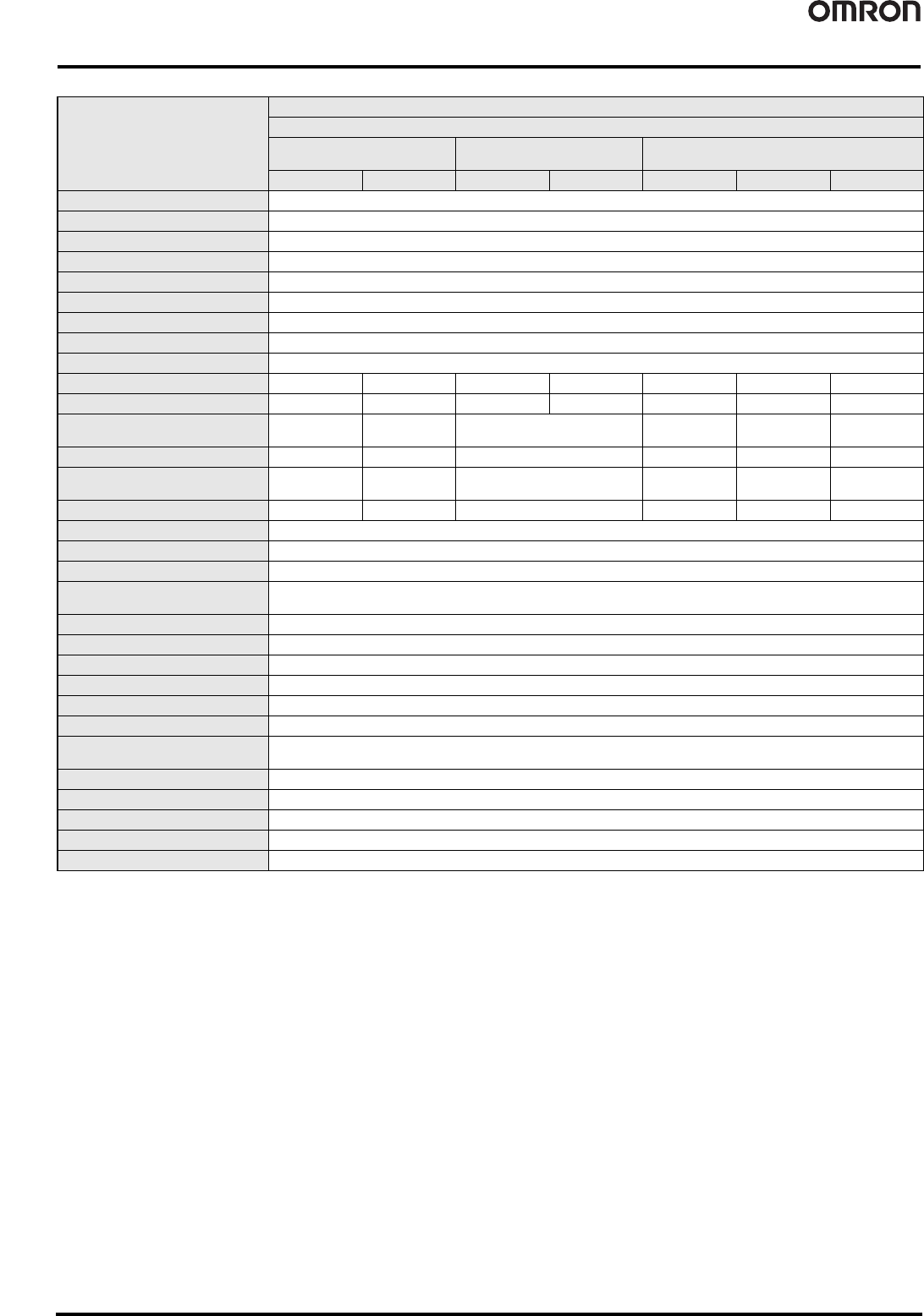
Smart Slaves DRT2 Series 15 OK: Function supported, ---: Function not supported. * The operation time monitor can be used with the DRT2- @ D04CL(-1). Notice: The contact operation counter function and the total ON time m…
14 Smart Slaves DRT2 Series
OK: Function supported, ---: Function not supported.
Notice: The contact operation counter function and the total ON time monitor function cannot be used simultaneously for the same contact.
Note: The DRT2-OD32SLH-1/MD32SLH-1 of unit version 2.0 or higher support External load short-circuit detection function.
Function
General Slaves
Screw-less clamp terminals
DRT2-@D16SLH
(Detection function)
DRT2-@D16SL
(No detection function)
DRT2-@D32SLH
(Detection function)
Input Output Input Output Input Output I/O
Operation time monitor OK
Contact operation counter OK
Unit conduction time monitor OK
Total ON time monitor OK
Unit comments OK
Connected device comments OK
Network power supply voltage monitor OK
I/O power supply monitor OK
Communications error log OK
Input filter OK --- OK --- OK --- OK
Power-ON inrush current protection OK --- OK --- OK --- OK
Sensor power supply short-circuit
detection
OK --- --- OK --- OK
External load disconnection detection OK --- --- OK --- OK
External load short-circuit detection --- OK --- ---
OK
(See Note.)
OK
(See Note.)
Disconnected sensor detection --- OK --- --- OK OK
Removable terminal block OK
Communications speed auto-detect OK
No need to wire Unit power supply OK
No need to wire input device power
supply
---
Expansion via Expansion I/O Units ---
Scaling ---
User compensation ---
Last maintenance date OK
Cumulative counter ---
Moving average processing ---
Number of A/D conversion points
(conversion cycle) setting
---
Peak/bottom hold ---
Top/valley hold ---
Percentage change calculation ---
Comparator ---
Selectable output value after error ---
Smart Slaves DRT2 Series 15
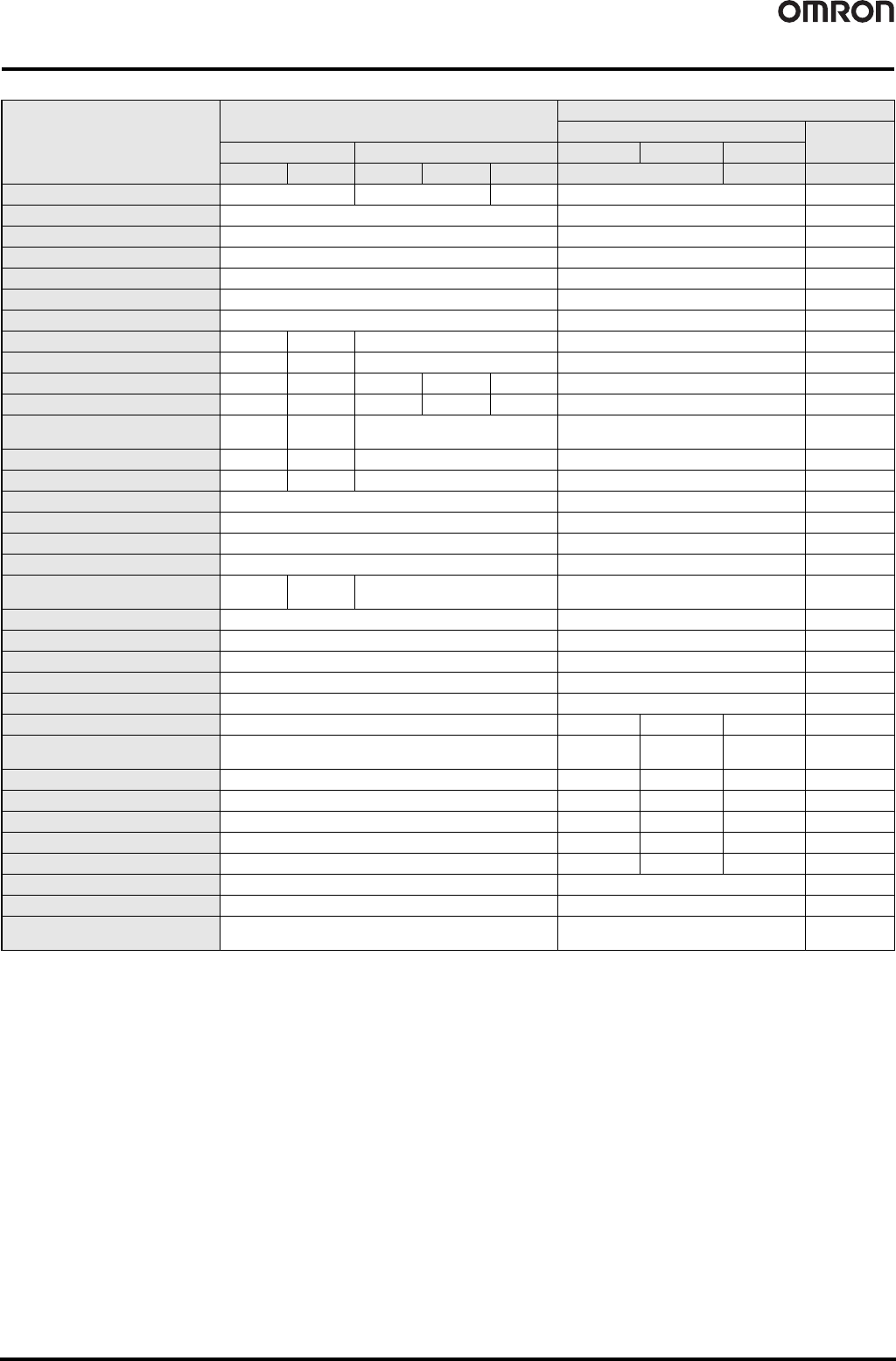
OK: Function supported, ---: Function not supported.
* The operation time monitor can be used with the DRT2-@D04CL(-1).
Notice: The contact operation counter function and the total ON time monitor function cannot be used simultaneously for the same contact.
Function
Environment-resistive Slaves
Analog Slaves
Analog I/O Terminals
Temperature
Input Terminals
Advanced Model Standard Model DRT2-AD04 DRT2-AD04H DRT2-DA02
Input Output Input Output I/O Input Output Input
Operation time monitor --- --- * OK --- ---
Contact operation counter OK --- ---
Unit conduction time monitor OK OK OK
Total ON time monitor OK --- ---
Unit comments OK OK OK
Connected device comments OK OK OK
Network power supply voltage monitor OK OK OK
I/O power supply monitor --- OK OK --- ---
Communications error log --- OK OK OK OK
Input filter OK --- OK --- OK --- ---
Power-ON inrush current protection OK --- OK --- OK --- ---
Sensor power supply short-circuit
detection
OK --- --- --- ---
External load disconnection detection OK --- --- --- ---
External load short-circuit detection --- OK --- --- ---
Disconnected sensor detection --- --- ---
Removable terminal block --- OK OK
Communications speed auto-detect OK OK OK
No need to wire Unit power supply OK OK OK
No need to wire input device power
supply
OK --- --- --- ---
Expansion via Expansion I/O Units --- --- ---
Scaling --- OK OK
User compensation --- OK OK
Last maintenance date OK OK OK
Cumulative counter --- OK OK
Moving average processing --- OK OK --- OK
Number of A/D conversion points
(conversion cycle) setting
--- OK --- --- ---
Peak/bottom hold --- OK OK --- OK
Top/valley hold --- OK OK --- OK
Percentage change calculation --- OK OK --- OK
Comparator --- OK OK --- OK
Selectable output value after error --- --- --- OK ---
Top/valley count --- --- OK
Operating time in preset temperature --- --- OK
Temperature difference detection
between input channels
--- --- OK
16 Smart Slaves DRT2 Series
Smart Slave Functions
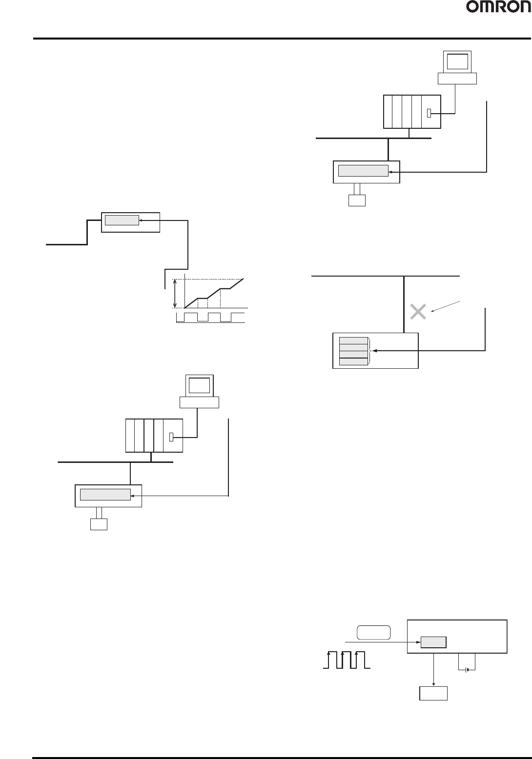
● Network Power Voltage Monitor
The present, bottom, and peak values of the Network power voltage
can be recorded in the Slave. Also, the monitor voltage can be set
using the CX-Integrator to maintain the monitor voltage in the slave
(default setting: 14 V), and a Status Area in the Unit will turn ON if
the voltage falls below the monitor voltage.
● Unit Conduction Time Monitor
The total ON time of the Slave's internal circuit power can be
calculated and recorded. (The CX-Integrator or explicit messages
can be used to read the information.)
Also, the monitor value can be maintained in the Slave, and a Status
Area will turn ON in the Unit when the total time reaches the set
value.
● Unit Comment Function
The user can assign and record a name or comment for every Unit
(up to 32 characters).
● Connected Device Comment Function
The user can assign a name for each of the Unit's I/O contacts (up to
32 characters) and record it in the Unit. The connected device can be
checked for each I/O contact, allowing faulty devices to be identified
during remote maintenance.
● Communication Error History Monitor
The error status information (communications error code and
communications power voltage when the error occurred) for the last
four communications errors that occurred can be recorded in the
Slave.
● Last Maintenance Date
This function enables writing to the Unit the date on which
maintenance was last performed. This means that the timing for
future maintenance can be judged more easily.
● Contact Operation Count Monitor Function
The Contact Operation Counter is used to count the number of times
each input or output contact changes from OFF to ON (maximum
sampling cycle: 50 Hz) and record the total value calculated in the
slave. (The CX-Integrator or explicit messages can be used to read
the information.)
The monitor value can be set in the slave, and when the set number
of operations is reached, a bit in the Status Area in the Unit will be
turned ON. (The CX-Integrator or explicit messages can be used to
read the details of the notification.)
• Counted operations: 0 to 4,294,967,295 operations
(Stored data: 0000 0000 to FFFF FFFF hex)
• Counting unit: One operation
Note 1: The Contact Operation Counter and Total ON Time Monitor cannot be used
at the same time for the same contact. Select the function to be used under
the Detection Mode heading.
Note 2: The Contact Operation Counter will operate only when the I/O power is ON.
Recorded in Slave
Total ON time
Total ON time
Internal circuit power
ON
OFF
DeviceNet
Slave
Slave
Unit comment
Recorded in Unit
CX-Integrator
DeviceNet
Unit comment
Slave
Connected device
comment
Recorded in Slave
CX-Integrator
DeviceNet
Connected device
comment
Connected device
Status when
communications error
occurred
Slave
Recorded in Slave
First error
Second error
Third error
Forth error
DeviceNet
ON
OFF
123
Slave
OFF
→
ON
Number of
operations
I/O power
Output device
(relay, etc.)
Recorded
in Slave
Number of times
output contact
changes to ON.