drt2_devicenet_q102-e1_20_22_csm2147.pdf - 第137页
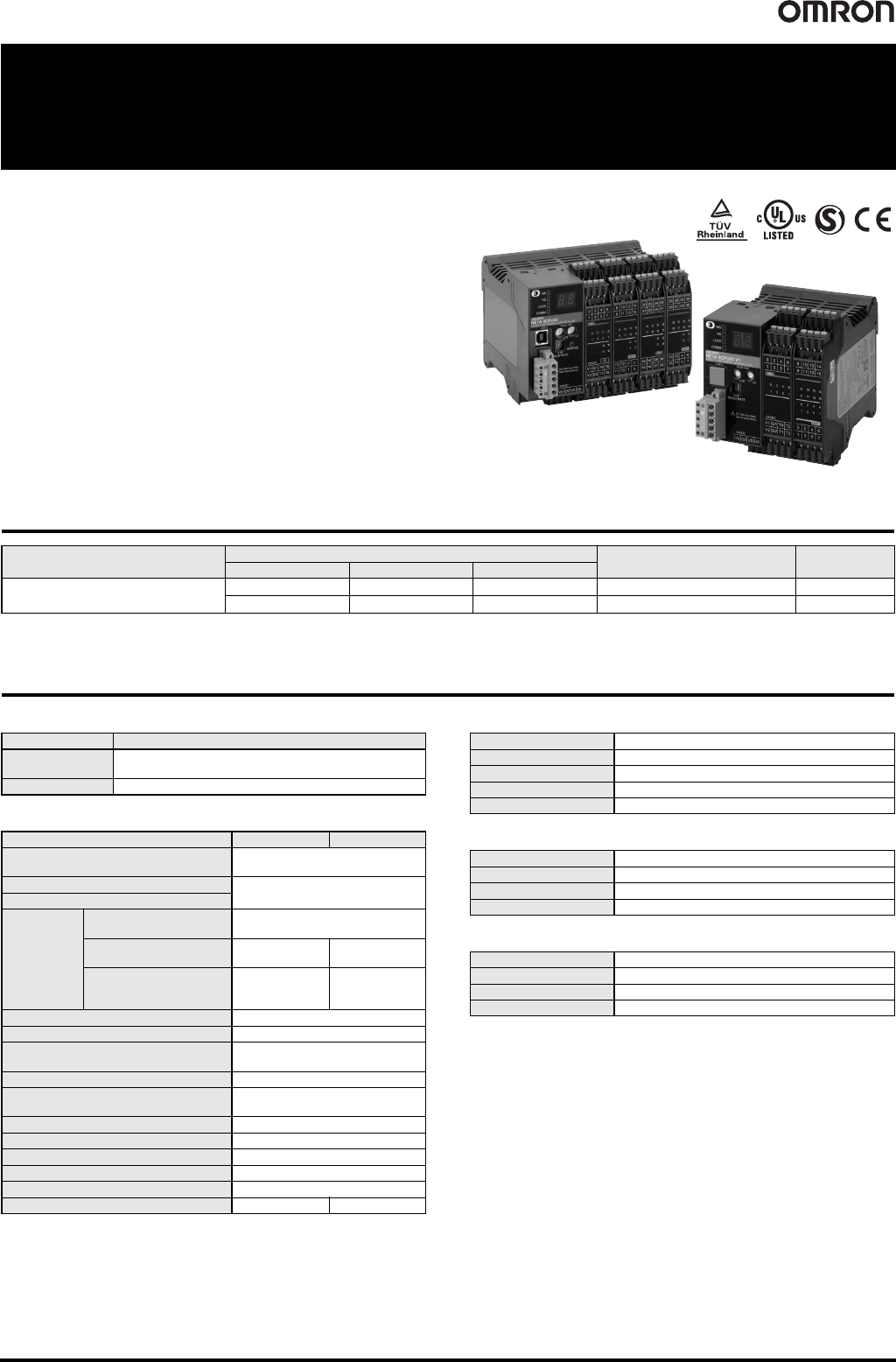
Safety Network Controller NE1A-SCPU Series 117 Safety Network Controller NE1A-SCPU Series Achieve Safety Control through Programming. • Compact Safety Controller. • The NE1A-SCPU01-V1 provides 16 built-in saf ety inputs …
116 Safety Network Controller NE0A-SCPU01
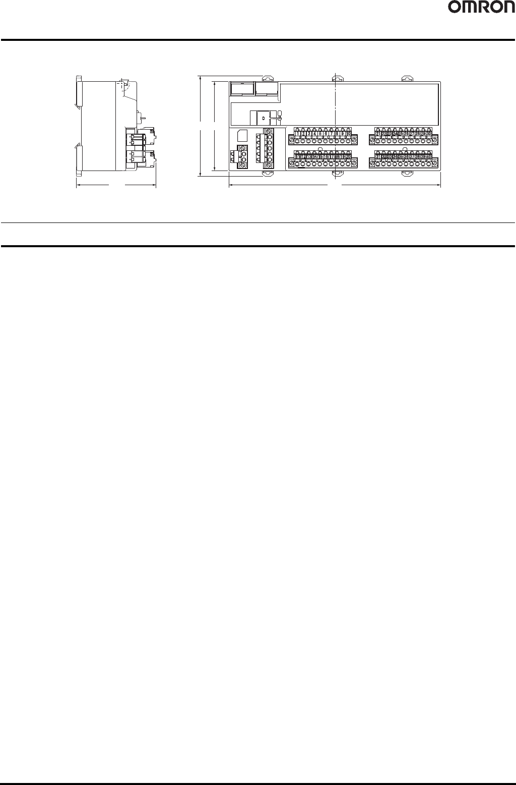
Dimensions (Unit: mm)
Safety Precautions
● Be sure to read the following operation manual for precautions and other details required for correct use of the Safety
Network Controller. CIP Safety on DeviceNet Safety Network Controller NE0A Series Operation Manual (Cat. No. Z916)
80
19071.4
(90)
NE0A-SCPU01
Safety Network Controller NE1A-SCPU Series 117
Safety Network Controller
NE1A-SCPU Series
Achieve Safety Control through
Programming.
• Compact Safety Controller.
• The NE1A-SCPU01-V1 provides 16 built-in safety inputs and 8 built-
in safety outputs.
The NE1A-SCPU02 provides 40 built-in safety inputs and 8 built-in
safety outputs.
• Reduced wiring with safety networks. Connect up to 32 Safety
Terminals.
• Monitor the safety system from Standard Controllers across the
network.
• ISO13849-1 (PLe) and IEC 61508 SIL3 certification.
Ordering Information
Note: The standard NE1A Controllers are equipped with spring-cage terminal blocks, but other screw terminal blocks are available if desired, e.g., to replace previous terminals.
Refer to Accessories.
Specifications
Certified Standards
General Specifications
*1. V0-G0: Internal control circuit
V1-G1 (G): For external input device, test output
V2-G2 (G): For external output device
The two ground terminals on the NE1A-SCPU02 are internally connected.
*2. Not including power consumption for external devices.
Safety Input Specifications
Safety Output Specifications
Test Output Specifications
* The maximum current for simultaneously ON outputs is 1.4 A.
(T0 to T3: NE1A-SCPU01-V1, T0 to T7: NE1A-SCPU02)
A 15 to 400-mA, 24-VDC external indicator can be connected to T3 and T7.
Name
I/O points
Model Unit version
Safety inputs Test outputs Safety outputs
Safety Network Controllers
16 4 8 NE1A-SCPU01-V1
Ver. 2.0
40 8 8 NE1A-SCPU02
Ver. 2.0
Certification body Standard
TÜV Rheinland
EN ISO 13849-1, EN ISO 13849-2, IEC 61508, EN 62061,
EN 61131-2, IEC 61326-3-1
UL
UL508, ISA12.12.01, UL1998, IEC 61508-3
Item Model NE1A-SCPU01-V1 NE1A-SCPU02
DeviceNet Communications power
supply voltage
11 to 25 VDC (supplied from the
communications connector)
Internal circuit power supply voltage (V0)
*
1
20.4 to 26.4 VDC
(24 VDC -15%/+10%)
I/O power supply voltage (V1, V2) *1
Current
consumption
Communications power
supply
24 VDC, 15 mA
Internal circuit power
supply
24 VDC, 230 mA 24 VDC, 280 mA
I/O power supply *2
24 VDC,
40 mA (Input)
120 mA (Output)
24 VDC,
80 mA (Input)
150 mA (Output)
Overvoltage category II
Noise immunity Conforms to IEC61131-2.
Vibration resistance
10 to 57 Hz: 0.35 mm,
57 to 150 Hz: 50 m/s
2
Shock resistance 150 m/s
2
: 11ms
Mounting method
DIN Track
(IEC 60715 TH35-7.5/TH35-15)
Ambient operating temperature -10°C to 55°C
Ambient operating humidity 10% to 95% (with no condensation)
Ambient storage temperature -40°C to 70°C
Degree of protection IP20
Serial interface USB Ver1.1
Weight 460 g max. 690 g max.
Input type Sinking inputs (PNP)
ON voltage 11 VDC min. between each terminal and ground
OFF voltage 5 VDC min. between each terminal and ground
OFF current 1 mA max.
Input current 4.5 mA
Output type Sourcing outputs (PNP)
Rated output current 0.5 A max./output
ON residual voltage 1.2 V max. between each output terminal and V2
Leakage current 0.1 mA max.
Output type Sourcing outputs (PNP)
Rated output current 0.7 A max./output *
ON residual voltage 1.2 V max. between each output terminal and V1
Leakage current 0.1 mA max.
118 Safety Network Controller NE1A-SCPU Series
DeviceNet Communications Specifications
Functions
Function Blocks
NE1A-SCPU-series Controller support the following logic functions and function blocks. Support depends on the unit version.
● Logic Functions ● Function Blocks
Communications protocol Conforms to DeviceNet
Connection form Multi-drop system and T-branch system can be combined (for trunk line and branch lines)
Baud rate 500/250/125 kbps
Communications media Special 5-wire cable (2 signal lines, 2 power supply lines, 1 shield line)
Communications distance
Communications power
supply
11 to 25 VDC
Maximum number of nodes 63
Safety I/O communications
(Pre-Ver. 1.0)
Safety Master function
• Max. no. of connections: 16
• Max. data size: Input 16 bytes or output 16 bytes (per connection)
• Connection type: Single-cast, multi-cast
Safety Slave function
• Max. no. of connections: 4
• Max. data size: Input 16 bytes or output 16 bytes (per connection)
• Connection type: Single-cast, multi-cast
Safety I/O communications
(unit version 1.0 or later)
Safety Master function
• Max. no. of connections: 32
• Max. data size: Input 16 bytes or output 16 bytes (per connection)
• Connection type: Single-cast, multi-cast
Safety Slave function
• Max. no. of connections: 4
• Max. data size: Input 16 bytes or output 16 bytes (per connection)
• Connection type: Single-cast, multi-cast
Standard I/O
communications
(all unit versions)
Standard Slave function
• Max. no. of connections: 2
• Max. data size: Input 16 bytes or output 16 bytes (per connection)
• Connection type: Poll, bit-strobe, COS, cyclic
Message communications Max. message length: 552 bytes
The values in parentheses are for Thin Cable.
Baud rate Network length (max.) Branch line length Total branch line length
500 kbps 100 m max. (100 m max.)
6 m max.
39 m max.
250 kbps 250 m max. (100 m max.) 78 m max.
125 kbps 500 m max. (100 m max.) 156 m max.
Name Function list entry
Supporting unit
versions
NOT
NOT
All
AND
AND
OR
OR
Exclusive OR
EXOR
Exclusive NOR
EXNOR
RS Flip-flop
RS-FF
1.0 or later
Comparator
Comparator
Name Function list entry
Supporting unit
versions
Reset
Reset
All
Restart
Restart
Emergency Stop
Monitoring
E-STOP
Light Curtain Monitoring
Light Curtain Monitoring
Safety Gate Monitoring
Safety Gate Monitoring
Two-hand Controller
Two Hand Controller
Off-Delay Timer
Off-Delay Timer
On-Delay Timer
On-Delay Timer
User Mode Switch
Monitoring
User Mode Switch
External Device Monitoring
EDM
Routing
Routing
Muting
Muting
1.0 or later
Enable Switch Monitoring
Enable Switch
Pulse Generator
Pulse Generator
Counter
Counter
Multiconnector
Multi Connector