drt2_devicenet_q102-e1_20_22_csm2147.pdf - 第70页
50 Environment-resistive Terminals wi th Transistors (High-function Typ e) DRT2- @ D08C(-1)/ @ D16C(-1) Wiring Diagrams DRT2-ID08C (NPN) DRT2-ID08C-1 (PNP) DRT2-OD08C (NPN) DRT2-OD08C-1 (PNP) DRT2-HD16C (NPN) DRT2-HD16C-…
Environment-resistive Terminals with Transistors (High-function Type)
DRT2-
@
D08C(-1)/@D16C(-1) 49
Input Specifications
● 8-point Inputs Terminals with Transistors ● 16-point Inputs Terminals with Transistors
Output Specifications
● 8-point Outputs Terminals with Transistors
Note: Refer to Peripheral Devices on page 169 for information on applicable connectors.
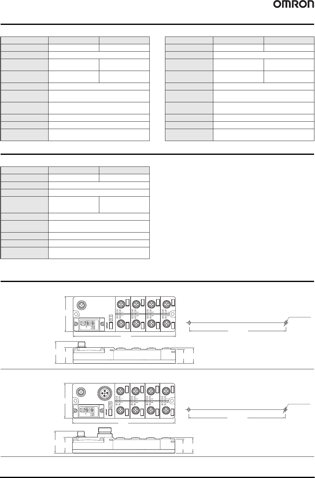
Dimensions (Unit: mm)
Item Model DRT2-ID08C DRT2-ID08C-1
Internal I/O common
NPN PNP
I/O points 8 inputs
ON voltage
9 VDC min. (between
input and V terminal)
9 VDC min. (between
input and G terminal)
OFF voltage
5 VDC max. (between
input and V terminal)
5 VDC max. (between
input and G terminal)
OFF current 1.0 mA max.
Input current
3.0 mA min./point (at 11 VDC)
11.0 mA max./point (at 24 VDC)
Power supply voltage
for sensor
Communications power supply voltage +0 V max.
Communications power supply voltage -1.5 V min.
ON delay time 1.5 ms max.
OFF delay time 1.5 ms max.
Number of circuits per
common
8 per common
Item Model DRT2-HD16C DRT2-HD16C-1
Internal I/O common
NPN PNP
I/O points 16 inputs
ON voltage
9 VDC min. (between
input and V terminal)
9 VDC min. (between
input and G terminal)
OFF voltage
5 VDC max. (between
input and V terminal)
5 VDC max. (between
input and G terminal)
OFF current 1.0 mA max.
Input current
3.0 mA min./point (at 17 VDC)
11.0 mA max./point (at 24 VDC)
Power supply voltage
for sensor
Communications power supply voltage +0 V max.
Communications power supply voltage -1.5 V min.
ON delay time 1.5 ms max.
OFF delay time 1.5 ms max.
Number of circuits per
common
16 per common
Item Model DRT2-OD08C DRT2-OD08C-1
Internal I/O common
NPN PNP
I/O points 8 inputs
Rated output current 1.5 A per point, 8.0 A per common
Residual voltage
1.2 V max. (1.5 A DC
between each output
terminal and G)
1.2 V max. (1.5 A DC
between each output
terminal and V)
Leakage current 0.1 mA max.
I/O power supply
voltage
20.4 to 26.4 VDC (24 VDC -15%/+10%)
ON delay time 0.5 ms max.
OFF delay time 1.5 ms max.
Number of circuits per
common
8 per common
Two, 5.3 dia. or M5
175
60
37.7
27.3
24.3
26.6
165±0.2
● Environment-resistive Terminals (8 or 16 Inputs)
DRT2-ID08C
DRT2-ID08C-1
DRT2-HD16C
DRT2-HD16C-1
Mounting Hole Dimension
175
60
43.9
27.3
24.3
26.6
Two, 5.3 dia. or M5
165±0.2
● Environment-resistive Terminals (8 Outputs)
DRT2-OD08C
DRT2-OD08C-1
Mounting Hole Dimension
50
Environment-resistive Terminals with Transistors (High-function Type)
DRT2-
@
D08C(-1)/@D16C(-1)
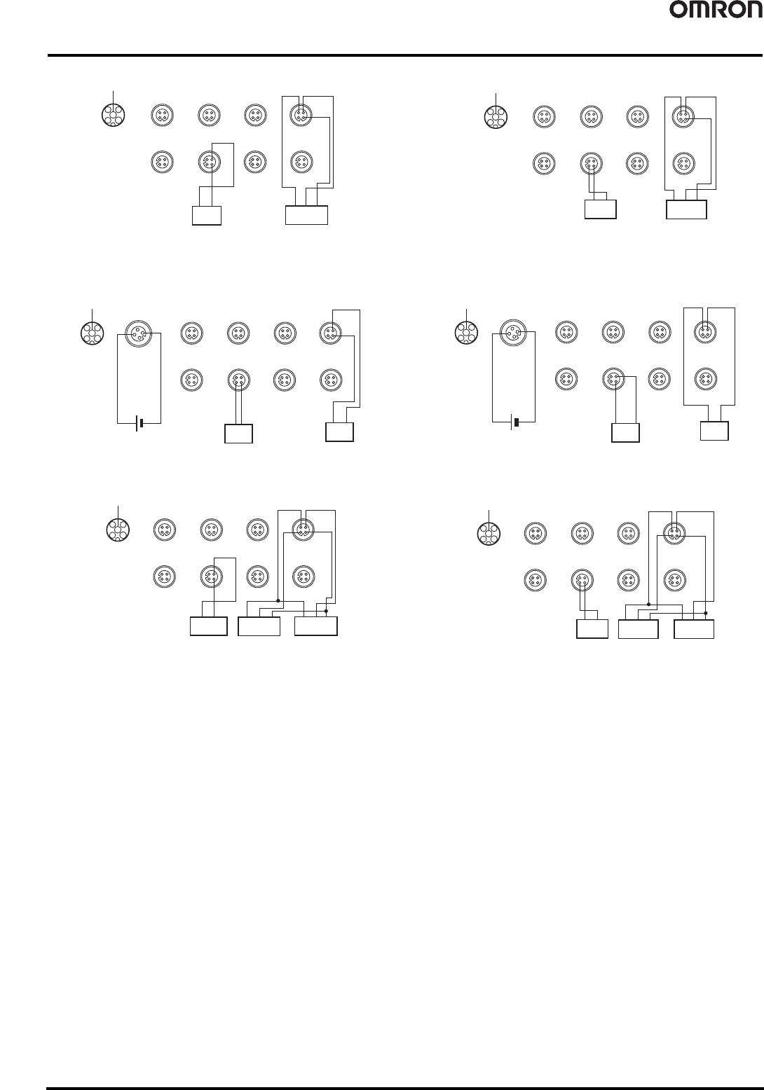
Wiring Diagrams
DRT2-ID08C (NPN) DRT2-ID08C-1 (PNP)
DRT2-OD08C (NPN) DRT2-OD08C-1 (PNP)
DRT2-HD16C (NPN) DRT2-HD16C-1 (PNP)
4
2
5
1
3
V+
CAN H
CAN L
V-
DRAIN
1
2
4
3
V
NC
G
Input
0
1
2
4
3
V
NC
G
Input
4
1
2
4
3
V
NC
G
Input
2
1
2
4
3
V
NC
G
Input 6
23
1
4
NC
V
G
Input 1
2 3
1
4
NC
V
G
Input 5
2 3
1
4
NC
V
G
Input 3
2
3
1
4
NC
V
G
Input 7
Two-wire sensor
(Limit switch, etc.)
Three-wire sensor with
NPN output
(e.g., photoelectric sensor
or proximity sensor)
Brown
(white)
Blue
(black)
Blue
(black)
Brown
(red)
Black
(White)
4
2
5
1
3
V+
CAN H
CAN L
V-
DRAIN
12
43
VNC
G
Input
0
12
43
VNC
G
Input
4
12
43
VNC
G
Input
2
1
2
4
3
V
NC
G
Input 6
23
1
4
NC
V
G
Input 1
23
1
4
NC
V
G
Input 5
23
1
4
NC
V
G
Input 3
2
3
1
4
NC
V
G
Input 7
Two-wire sensor
(Limit switch, etc.)
Three-wire sensor with
NPN output
(e.g., photoelectric sensor
or proximity sensor)
Brown
(white)
Blue
(black)
Blue
(black)
Brown
(red)
Black
(White)
4
2
5
1
3
V+
CAN H
CAN L
V-
DRAIN
12
43
V
Output 4
12
43
V
Output 2
12
43
V
Output 6
23
14
NC
V Output 1
23
14
Output 5
23
14
V Output 3
23
14
V
Output 7
Solenoid valve, etc.
Solenoid valve, etc.
12
43
V
Output 0
2
NC
1
0V
3
24V
4
NC
I/O power supply
NC
NC
NC
NC
NC
NC NC
NC
NC NC
NC NC
NC
NC NC
4
2
5
1
3
V+
CAN H
CAN L
V-
DRAIN
12
43
Output 4
12
43
Output 2
1
2
4
3
Output 6
23
14
NC
Output 1
23
14
Output 5
23
14
Output 3
23
14
Output 7
Solenoid valve, etc.
Solenoid valve, etc.
12
43
Output 0
2
NC
1
0V
3
24V
4
NC
I/O power supply
NCNC
NC
NCNC
NC
NC
NCNC
NC
NC
NCNC
NC
NC
G
G
GG
G
GG G
4
2
5
1
3
1
2
4
3
V
G
Input 0
1
2
4
3
V
G
Input 8
1
2
4
3
V
G
Input 4
1
2
4
3
V
G
Input
12
2
3
1
4
V
G
Input 2
2
3
1
4
V
G
Input 10
2
3
1
4
V
G
Input 6
2
3
1
4
V
G
Input 14
V+
CAN H
CAN L
V-
DRAIN
Two-wire sensor
(Limit switch, etc.)
Three-wire sensor
with NPN output
(e.g., photoelectric
sensor or proximity
sensor)
Input 1
Input 3
Input 5
Input 9
Input 13
Input 15
Input 11
Input 7
Three-wire sensor
with NPN output
(e.g., photoelectric
sensor or proximity
sensor)
Blue
(black)
Brown
(red)
Black
(White)
Blue
(black)
Brown
(red)
Black
(White)
Brown
(white)
Blue
(black)
4
2
5
1
3
V+
CAN H
CAN L
V-
DRAIN
12
43
V
G
Input 0
12
4
3
V
G
Input 8
12
43
V
G
Input 4
1
2
4
3
V
G
Input 12
23
14
V
G
Input 2
23
14
V
G
Input 10
23
14
V
G
Input 6
2
3
1
4
V
G
Input 14
Input 1
Input 3
Input 5 Input 9
Input 13
Input 15
Input 11
Input 7
Two-wire sensor
(Limit switch, etc.)
Three-wire sensor
with PNP output
(e.g., photoelectric
sensor or proximity
sensor)
Three-wire sensor
with PNP output
(e.g., photoelectric
sensor or proximity
sensor)
Blue
(black)
Brown
(red)
Black
(White)
Blue
(black)
Brown
(red)
Black
(White)
Brown
(white)
Blue
(black)
Environment-resistive Terminals with Transistors (Standard Type)
DRT2-
@
D04CL(-1)/
@
D08CL(-1)/
@
D16CL(-1)
51
Environment-resistive Terminals with Transistors (Standard Type)
DRT2-
@
D04CL(-1)/
@
D08CL(-1)/
@
D16CL(-1)
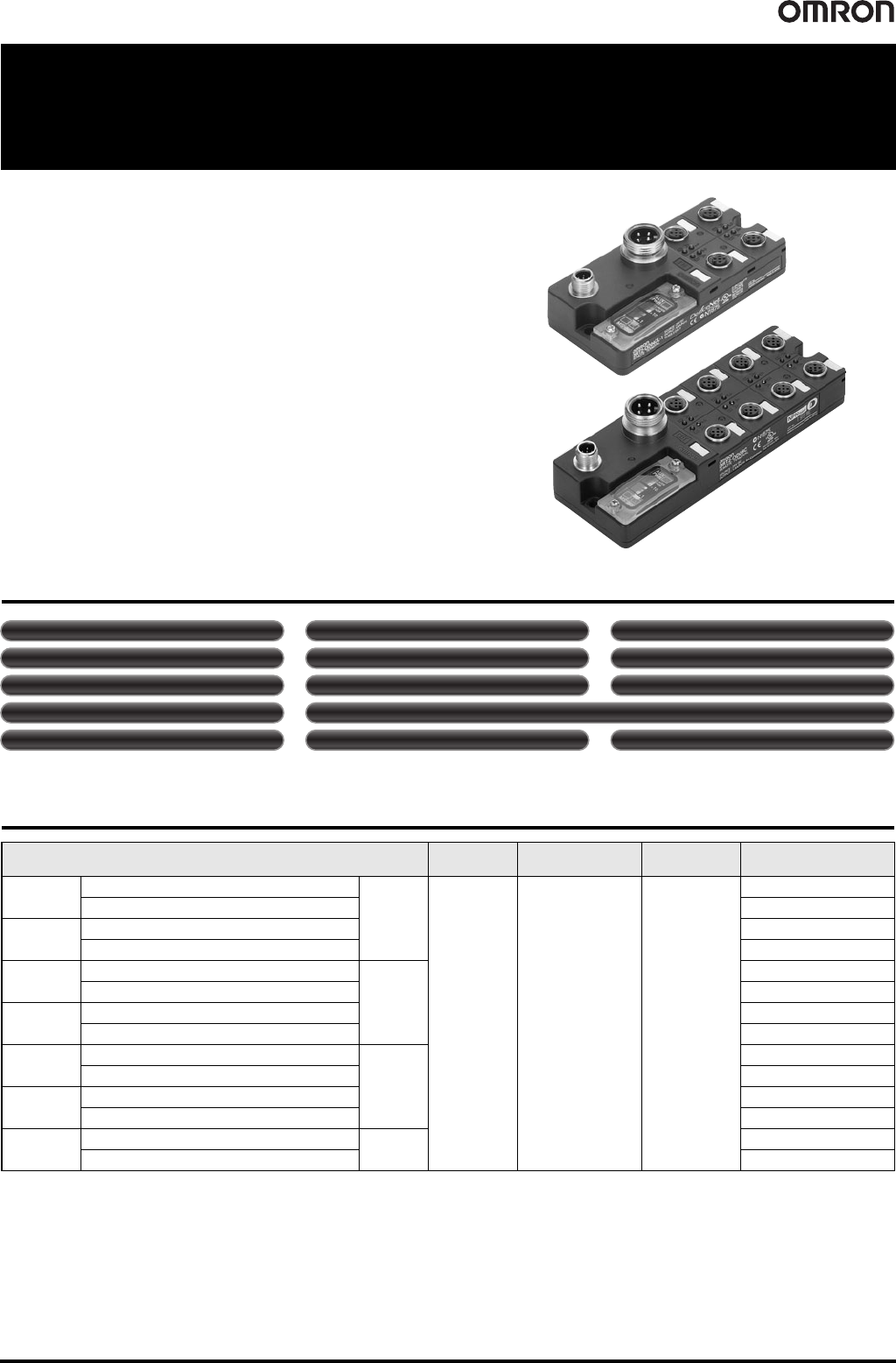
Remote I/O Terminals with High
Degree of Environmental Resistance
(IP67) in Product Lineup Including
Economical Input, Output, and Mixed
I/O Models
• Common Smart Slave functionality provides strong support for equipment
operation status monitoring and effective maintenance.
• High degree of environmental resistance with dust-proof and drip-proof
construction. (IP67)
• Models with one connector for two outputs are available to make easier
connection with hydraulic valve devices. (Models with 16 outputs and models
with 16 mixed I/O)
Smart Slave Functions
* The operation time monitor can be used with the DRT2-@D04CL(-1).
Ordering Information
Specifications I/O connections
Rated internal circuit
power supply voltage
Rated I/O power
supply voltage
Model
Inputs
NPN (+ common)
4 points
Sensor I/O
connector
Supplied from the
communications
connector
24 VDC
DRT2-ID04CL
PNP (- common) DRT2-ID04CL-1
Outputs
NPN (- common) DRT2-OD04CL
PNP (+ common) DRT2-OD04CL-1
Inputs
NPN (+ common)
8 points
DRT2-ID08CL
PNP (- common) DRT2-ID08CL-1
Outputs
NPN (- common) DRT2-OD08CL
PNP (+ common) DRT2-OD08CL-1
Inputs
NPN (+ common)
16 points
DRT2-HD16CL
PNP (- common) DRT2-HD16CL-1
Outputs
NPN (- common) DRT2-WD16CL
PNP (+ common) DRT2-WD16CL-1
I/O
NPN (input: + common, output: - common)
8 inputs/
8 outputs
DRT2-MD16CL
PNP (input: - common, output: + common) DRT2-MD16CL-1
Operation time monitor (I/O only) * Contact operation counter Unit conduction time monitor
Total ON time monitor Unit comments Connected device comments
Network power supply voltage monitor I/O power supply monitor function Communications error log function
Input filter (input or I/O only) Power-ON inrush current protection (input or I/O only)
Communications speed auto-detection No need to wire Unit power supply Last maintenance date