drt2_devicenet_q102-e1_20_22_csm2147.pdf - 第79页
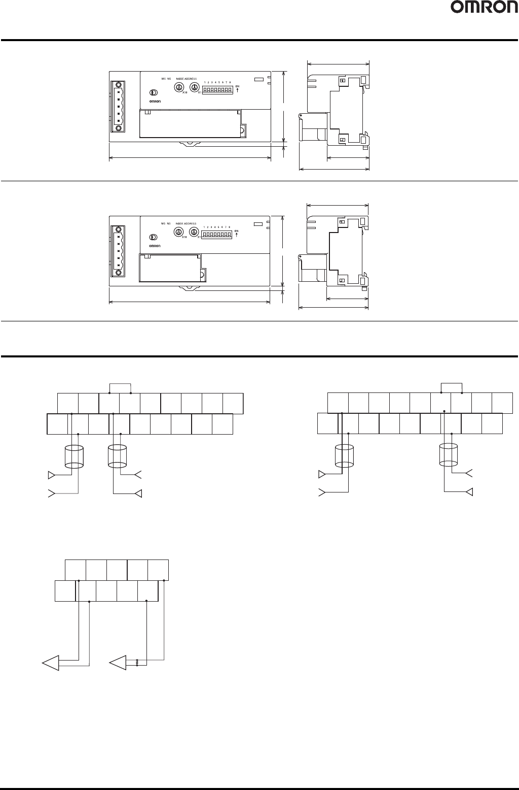
Analog I/O Terminals DRT2-AD04(H)/DA02 59 Dimensions (Unit: mm) Wiring Diagrams DRT2-AD04 DRT2-AD04H DRT2-D A02 115 49.7 29.9 43.9 50 3.1 DRT 2-AD04 DRT 2-AD04H 115 50 3.1 43.9 29.9 49.7 DRT 2-DA0 2 AG NC I0 + I1 + I2 + …
58 Analog I/O Terminals DRT2-AD04(H)/DA02
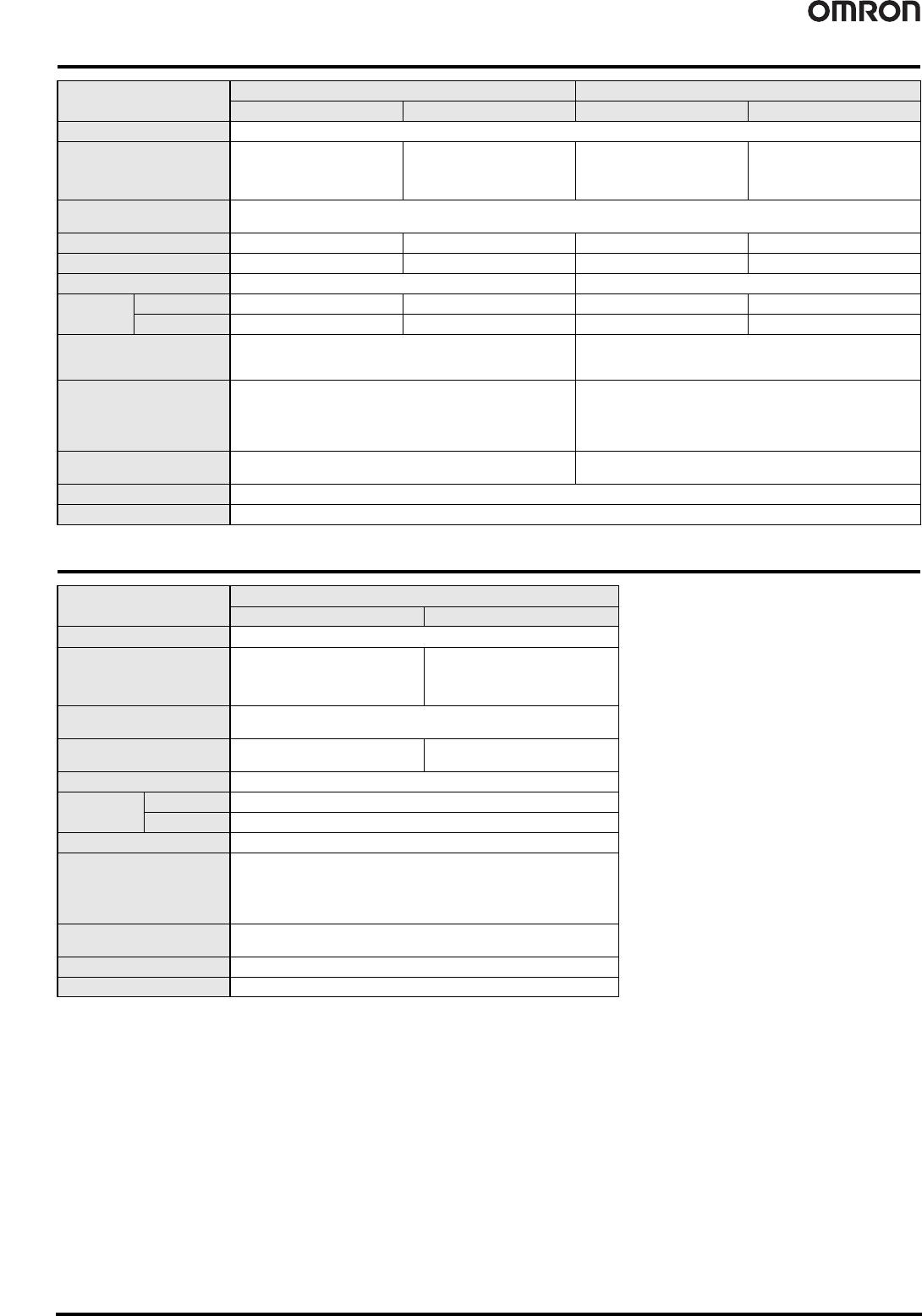
Input Specifications
Output Specifications
Model DRT2-AD04 DRT2-AD04H
Item Specifications Voltage input Current input Voltage input Current input
Input points 4 points (inputs 0 to 3)
Input type
0 to 5 V
1 to 5 V
0 to 10 V
-10 to +10 V
0 to 20 mA
4 to 20 mA
0 to 5 V
1 to 5 V
0 to 10 V
0 to 20 mA
4 to 20 mA
Input range setting method
• Set using DIP switches: Shared by inputs 0 and 1, shared by inputs 2 and 3
• Set using the Configurator: Possible to set inputs 0 to 3 independently
Maximum signal input ±15 V ±30 mA ±15 V ±30 mA
Input impedance 1 M min. Approx. 250 1 M min. Approx. 250
Resolution 1/6,000 (FS) 1/30,000 FS (full scale)
Overall
accuracy
25°C ±0.3% FS ±0.4% FS ±0.3% FS ±0.4% FS
-10°C to 55°C ±0.6% FS ±0.8% FS ±0.6% FS ±0.8% FS
Conversion time
4 ms max. for 4 inputs
Note: When calculation functions are not used and the DeviceNet
communications cycle is 4 ms.
250 ms max. for 4 inputs
Converted data
Input ranges other than -10 to 10 V:Full scale is 0000 to 1770
hexadecimal (0 to 6,000)
-10 to 10 V input range: Full scale is F448 to 0BB8
hexadecimal (-3,000 to 3,000)
A/D conversion range: ±5% FS
Full scale is 0000 to 7530 hexadecimal
A/D conversion range: ±5% FS
Insulation method
Photocoupler isolation between inputs and communications lines
(There is no isolation between input signals)
Photocoupler isolation (between inputs and communications lines
and between temperature input signals)
I/O connections Terminal block
Accessories Four shorting bars for use with current inputs.
Model DRT2-DA02
Item Specifications Voltage output Current output
Output points 2 points (output 0 and1)
Output type
0 to 5 V
1 to 5 V
0 to 10 V
-10 to 10 V
0 to 20 mA
4 to 20 mA
Input range setting method
• Set using DIP switches: Independent for outputs 0 and 1
• Set using the Configurator: Independent for outputs 0 and 1
Allowable output load
resistance
1 K min. 600 max.
Resolution 1/6,000 (FS)
Overall
accuracy
25°C ±0.4% full scale
-10°C to 55°C ±0.8% full scale
Conversion time 2 ms/2 points
Converted data
Output ranges other than -10 to 10 V: Full scale is 0000 to 1770 hexadecimal
(0 to 6,000)
-10 to 10 V output range: Full scale is F448 to 0BB8 hexadecimal
(-3,000 to 3,000)
D/A conversion range: ±5% FS
Insulation method
Photocoupler isolation between outputs and communications lines
(There is no isolation between output signals)
I/O connections Terminal block
Accessories None
Analog I/O Terminals DRT2-AD04(H)/DA02 59
Dimensions (Unit: mm)
Wiring Diagrams
DRT2-AD04 DRT2-AD04H
DRT2-DA02
115
49.7
29.9
43.9
50
3.1
DRT2-AD04
DRT2-AD04H
115
50
3.1
43.9
29.9
49.7
DRT2-DA02
AG NC
I0
+
I1
+
I2
+
V3
+
V1
+
V2
+
V2
-
V1
-
AG
V0
+
V0
-
AG
V3
-
AG
I3
+
NC
Shorted
Voltage input
0 V
0 V
Current input
Note: With using a current input, always short the V+ and I+ terminals.
(Use the shorting bar provided with the Unit.)
NC NC
I0
+
I1
+
V2
+
V3
+
V1
+
V1
-
NC
V0
+
V0
-
NC
V3
-
I3
+
Voltage input
0 V
0 V
Current input
NC
NC
V2
-
I2
+
Shorted
Note: With using a current input, always short the V+ and I+ terminals.
(Use the shorting bar provided with the Unit.)
+
-
+
-
External
device
Using a voltage
output from output 0
Using a current
output from output 1
NC
I0
+
V1
+
I1
+
1
-
NC
V0
+
0
-
NC
NC
External
device
Note: The voltage and current output ranges (signals) are set with
either the DIP switch or the Configurator settings.
60 Temperature Input Terminals DRT2-TS04@
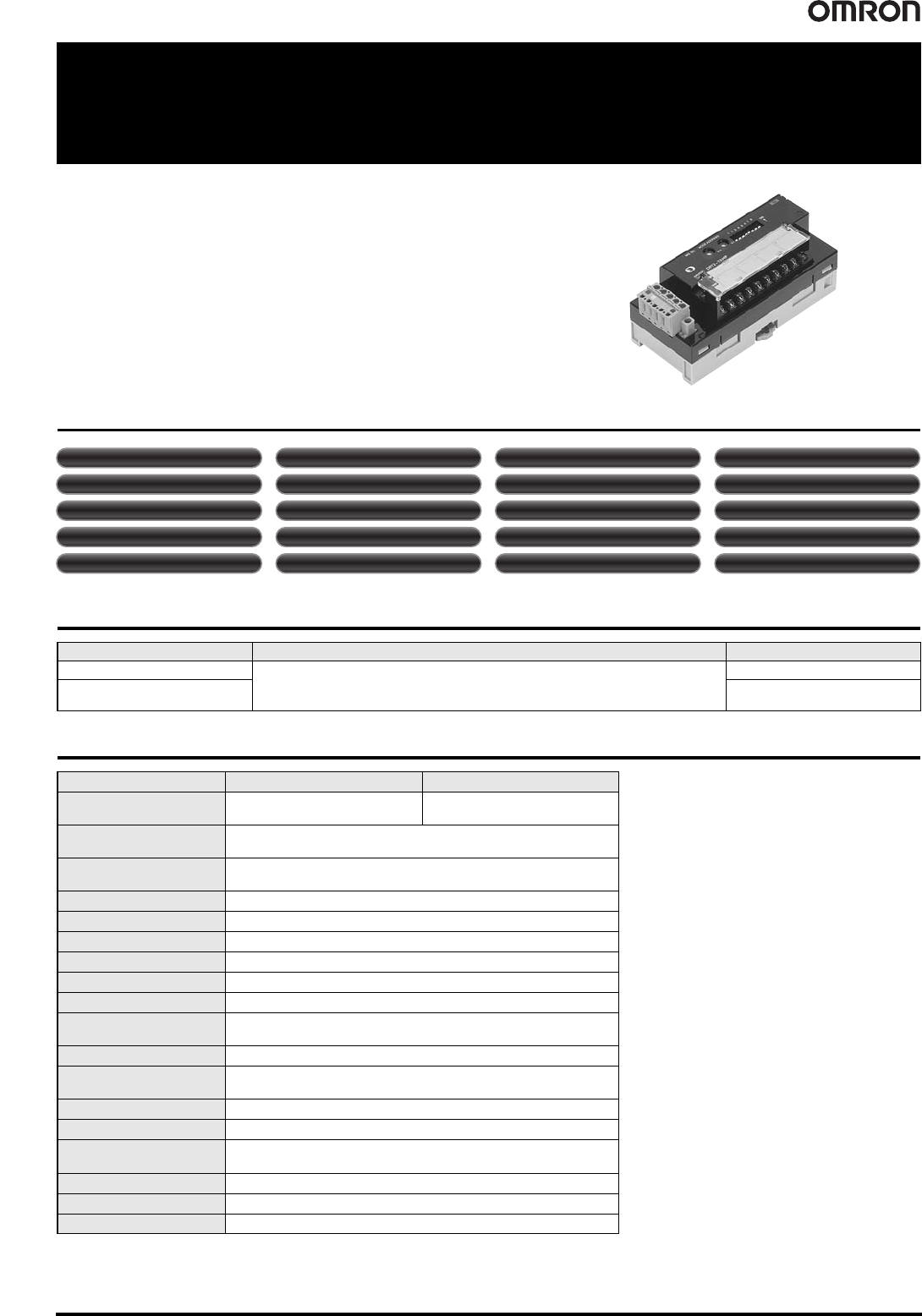
Temperature Input Terminals
DRT2-TS04@
Temperature Input Terminal with Smart
Functionality
• The Temperature Input Terminal can be used with almost the same functionality as a
Analog Input Terminal, such as with scaling and comparator functions.
• Enhanced performance is provided with functionality specific to the Temperature
Input Terminal, such as the recording the operating time in a preset temperature
range and temperature difference detection between input channels.
Smart Slave Functions
Ordering Information
General Specifications
Input type I/O points Model
Thermocouple input
4 inputs allocated 4 input words at the Master Unit
(8 input words allocated when 1/100 display mode is selected).
DRT2-TS04T
Platinum-resistance
thermometer input
DRT2-TS04P
Item Model DRT2-TS04T DRT2-TS04P
Input type Thermocouple input
Platinum-resistance thermometer
input
I/O points
4 inputs allocated 4 input words at the Master Unit
(8 input words allocated when 1/100 display mode is selected)
Communications power
supply voltage
11 to 25 VDC (Supplied from the communications connector)
Current consumption 70 mA max. (24 VDC), 110 mA max. (11 VDC)
Noise immunity Conforms to IEC61000-4-4, 2.0 kV
Vibration resistance 10 to 150 Hz, 0.7-mm single amplitude
Shock resistance 150 m/s
2
Dielectric strength 500 VAC (between isolated circuits)
Insulation resistance 20 MΩ min. (initial value) at 100 VDC
Ambient operating
temperature
-10°C to 55°C (with no icing or condensation)
Ambient operating humidity 25% to 85%
Ambient operating
atmosphere
No corrosive gases
Ambient storage temperature -25°C to 65°C
Mounting method DIN 35 mm-track mounting
Mounting strength
50 N
10 N (in the DIN Track direction)
Screw tightening torque M3: 0.5 N·m
Terminal strength No damage when 50 N pull load was applied.
Weight 160 g max.
Unit conduction time monitor Unit comments Connected device comments
Network power supply voltage monitor
Communications error log function Removable terminal block
Communications speed auto-detection
No need to wire Unit power supply
Scaling User calibration Last maintenance date Integration
Moving averaging
Comparator Top/valley count
Operating time in preset temperature range
Temperature difference detection between input channels
Peak/bottom hold Top/valley hold Rate of change calculation