drt2_devicenet_q102-e1_20_22_csm2147.pdf - 第49页
Transistor Remote I/O Terminals with 3- tier Terminal Blocks DRT2- @ D16TA(-1) 29 Input Specifications ● 16-point Inputs T erminals with T ransistor s ● 8-point In puts/8-point Outp uts T erminals with T ransistor s Outp…
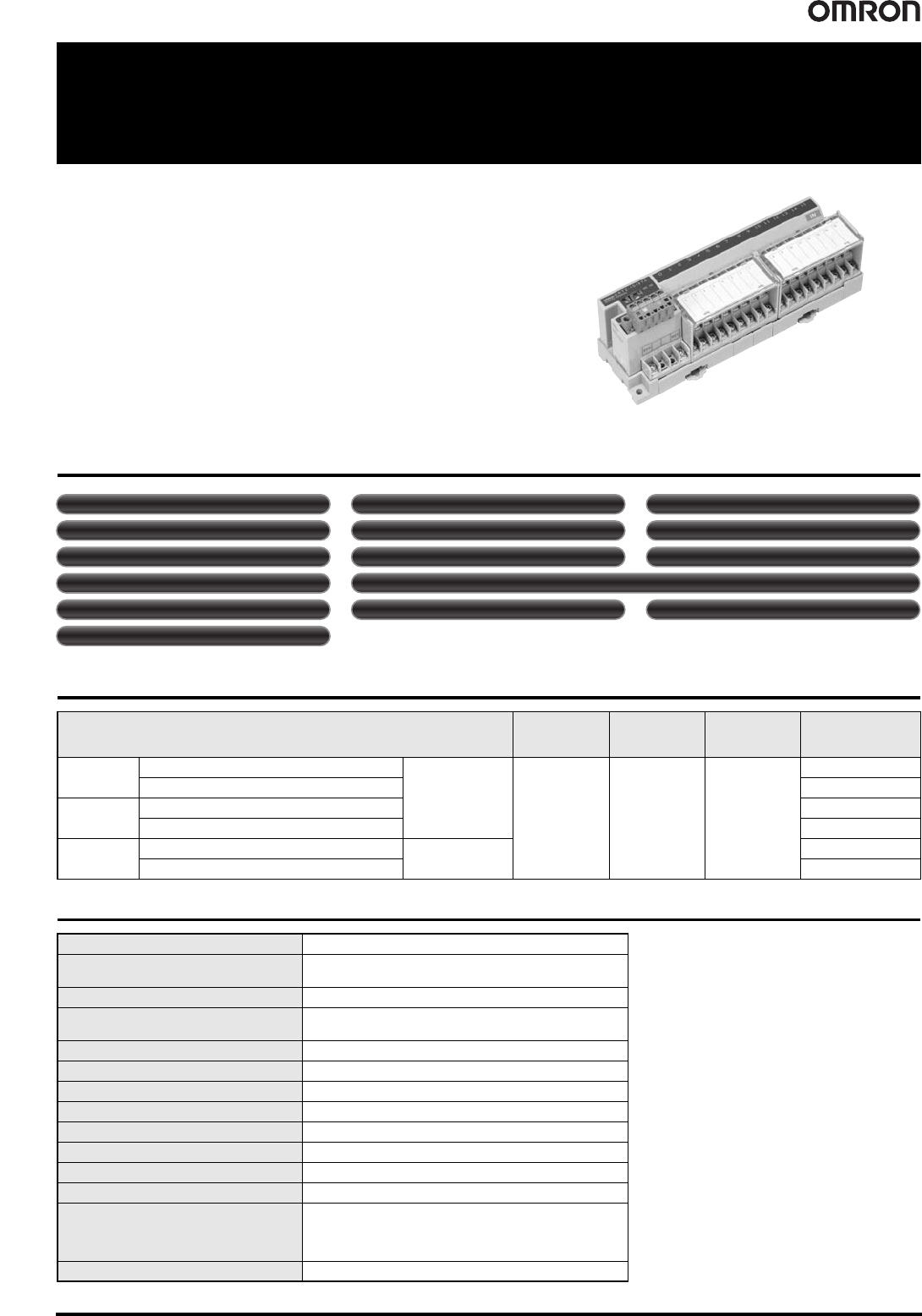
28 Transistor Remote I/O Terminals with 3-tier Terminal Blocks DRT2-@D16TA(-1)
Transistor Remote I/O Terminals with 3-tier Terminal Blocks
DRT2-@D16TA(-1)
A Smart Slave with a 3-tier Terminal
Block That Means Wiring Locations
Are Easy to Understand with No
Sharing of Terminals.
• Easy wiring with no sharing of terminals. Easy-to-understand wiring
locations.
• No relay terminal block terminals required.
• Detachable cassette-type circuit sections.
Smart Slave Functions
Ordering Information
General Specifications
Specifications I/O connections
Rated internal
circuit power
supply voltage
I/O power supply
voltage
Model
Inputs
NPN (+ common)
16 points
M3
screw terminals
Supplied from
Basic Unit.
24 VDC
DRT2-ID16TA
PNP (- common) DRT2-ID16TA-1
Outputs
NPN (- common) DRT2-OD16TA
PNP (+ common) DRT2-OD16TA-1
I/O
NPN (input: + common, output: - common)
Input: 8 points/
Output: 8 points
DRT2-MD16TA
PNP (input: - common, output: + common) DRT2-MD16TA-1
Communications power supply voltage 11 to 25 VDC (Supplied from communications connector)
Communications power supply current
consumption
45 mA max. (24 VDC), 80 mA max. (11 VDC)
Noise immunity Conforms to IEC61000-4-4, 2 kV (power line)
Vibration resistance
10 to 60 Hz, 0.7-mm double amplitude, 60 to 150 Hz, 50 m/s
2
for
80 min each in the X, Y, and Z directions
Shock resistance 150 m/s
2
(3 times each in 6 directions on 3 axes)
Dielectric strength 500 VAC (between isolated circuits)
Insulation resistance 20 MΩ min. (between isolated circuits)
Ambient operating temperature -10°C to 55°C
Ambient operating humidity 25% to 85% (with no condensation)
Ambient atmosphere No corrosive gases
Ambient storage temperature -25°C to 65°C
Mounting method DIN 35 mm-track mounting, M4 screw mounting
Screw tightening torque
M2 (communications connector screws): 0.26 to 0.3 N
·m
M3 (screw terminals): 0.5 N
·m
M3 (screw terminals): 0.5 N
·m
M4 (unit mounting): 0.6 to 0.98 N
·m
Weight 300 g max.
Power-ON inrush current protection (input or I/O only)
Operation time monitor Contact operation counter Unit conduction time monitor
Total ON time monitor Unit comments Connected device comments
Network power supply voltage monitor I/O power supply monitor function Communications error log function
Input filter (input or I/O only)
Removable terminal block Communications speed auto-detection No need to wire Unit power supply
Last maintenance date
Transistor Remote I/O Terminals with 3-tier Terminal Blocks DRT2-@D16TA(-1) 29
Input Specifications
● 16-point Inputs Terminals with Transistors ● 8-point Inputs/8-point Outputs Terminals with
Transistors
Output Specifications
● 16-point Outputs Terminals with Transistors ● 8-point Inputs/8-point Outputs Terminals with
Transistors
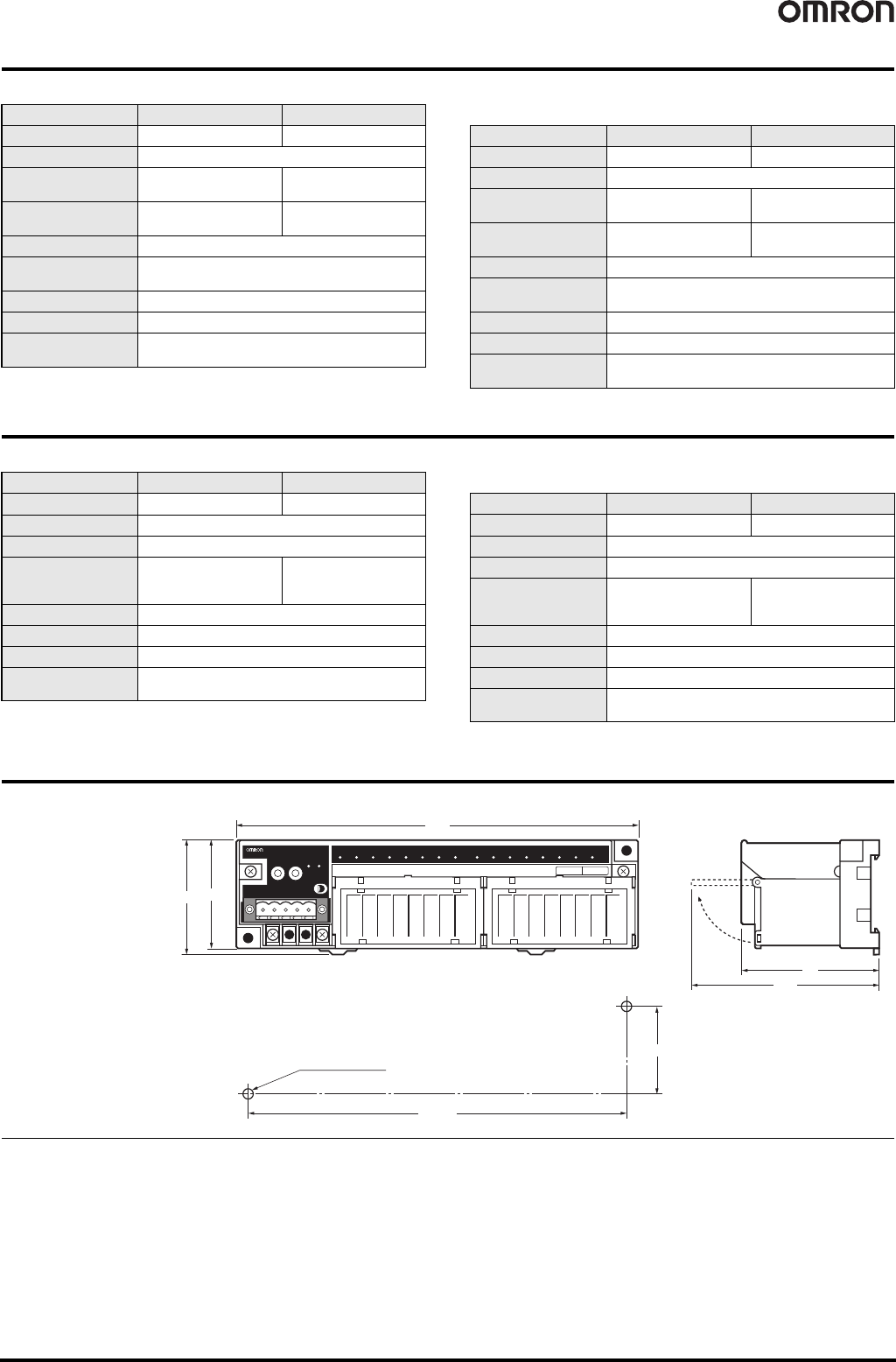
Dimensions (Unit: mm)
Item Model DRT2-ID16TA DRT2-ID16TA-1
Internal I/O common
NPN PNP
I/O points 16 inputs
ON voltage
15 VDC min. (between
input and V terminal)
15 VDC min. (between
input and G terminal)
OFF voltage
5 VDC max. (between
input and V terminal)
5 VDC max. (between
input and G terminal)
OFF current 1.0 mA max.
Input current
24 VDC: 6.0 mA max./point
17 VDC: 3.0 mA max./point
ON delay time 1.5 ms max.
OFF delay time 1.5 ms max.
Number of circuits per
common
8 per common
Item Model DRT2-MD16TA DRT2-MD16TA-1
Internal I/O common
NPN PNP
I/O points 8 inputs
ON voltage
15 VDC min. (between
input and V terminal)
15 VDC min. (between
input and G terminal)
OFF voltage
5 VDC max. (between
input and V terminal)
5 VDC max. (between
input and G terminal)
OFF current 1.0 mA max.
Input current
24 VDC: 6.0 mA max./point
17 VDC: 3.0 mA max./point
ON delay time 1.5 ms max.
OFF delay time 1.5 ms max.
Number of circuits per
common
8 per common
Item Model DRT2-OD16TA DRT2-OD16TA-1
Internal I/O common
NPN PNP
I/O points 16 outputs
Rated output current 0.5 A/point
Residual voltage
1.2 VDC max.
(0.5 A DC between output
and G terminal)
1.2 VDC max.
(0.5 A DC between output
and V terminal)
Leakage current 0.1 mA max.
ON delay time 0.5 ms max.
OFF delay time 1.5 ms max.
Number of circuits per
common
8 per common
Item Model DRT2-MD16TA DRT2-MD16TA-1
Internal I/O common
NPN PNP
I/O points 8 outputs
Rated output current 0.5 A/point
Residual voltage
1.2 VDC max.
(0.5 A DC between output
and G terminal)
1.2 VDC max.
(0.5 A DC between output
and V terminal)
Leakage current 0.1 mA max.
ON delay time 0.5 ms max.
OFF delay time 1.5 ms max.
Number of circuits per
common
8 per common
Two, 4.2-dia. or M4
Mounting Hole Dimension
0 1 2 3 4 5 6 7 8 9 10 11 12 13 14 15
IN
DRT2-ID16TA
REMOTE TERMINAL DC24V
NS
MS
0 1 2 3 4 5 6 7 8 9 10 11 12 13 14 15
180
50
(54)
170
±0.2
40
±0.2
58
(83)
( ) Dimensions in parentheses
are reference values.
DRT2-ID16TA(-1)
DRT2-OD16TA(-1)
DRT2-MD16TA(-1)
30 Transistor Remote I/O Terminals with 3-tier Terminal Blocks DRT2-@D16TA(-1)
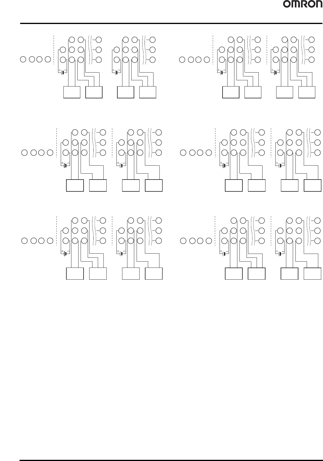
Wiring Diagrams
DRT2-ID16TA (NPN) DRT2-ID16TA-1 (PNP)
DRT2-OD16TA (NPN) DRT2-OD16TA-1 (PNP)
DRT2-MD16TA (NPN) DRT2-MD16TA-1 (PNP)
7
V1
G1
1
V1
G1
0
V1
G1
V1
G1
15
V2
G2
9
V2
G2
8
V2
G2
V2
G2
Two-wire sensor
(Limit switch, etc.)
Sensor with
NPN output
(e.g., photoelectric
sensor or proximity sensor)
Two-wire sensor
(Limit switch, etc.)
Sensor with
NPN output
(e.g., photoelectric
sensor or proximity sensor)
Brown
(White)
Blue
(black)
Brown
(White)
Blue
(black)
Blue
(Black)
Brown
(Red)
Black
(White)
Blue
(Black)
Brown
(Red)
Black
(White)
7
V1
G1
1
V1
G1
0
V1
G1
V1
G1
15
V2
G2
9
V2
G2
8
V2
G2
V2
G2
Two-wire sensor
(Limit switch, etc.)
Sensor with
PNP output
(e.g., photoelectric
sensor or proximity sensor)
Two-wire sensor
(Limit switch, etc.)
Sensor with
PNP output
(e.g., photoelectric
sensor or proximity sensor)
Brown
(White)
Blue
(black)
Brown
(White)
Blue
(black)
Blue
(Black)
Brown
(Red)
Black
(White)
Blue
(Black)
Brown
(Red)
Black
(White)
7
V1
G1
1
V1
G1
0
V1
G1
V1
G1
15
V2
G2
9
V2
G2
8
V2
G2
V2
G2
Solenoid
valve, etc.
Solenoid
valve, etc.
Solenoid
valve, etc.
Solenoid
valve, etc.
7
V1
G1
1
V1
G1
0
V1
G1
V1
G1
15
V2
G2
9
V2
G2
8
V2
G2
V2
G2
Solenoid
valve, etc.
Solenoid
valve, etc.
Solenoid
valve, etc.
Solenoid
valve, etc.
7
V2
G2
1
V2
G2
0
V2
G2
V2
G2
7
V1
G1
1
V1
G1
0
V1
G1
V1
G1
Solenoid
valve, etc.
Solenoid
valve, etc.
Two-wire sensor
(Limit switch, etc.)
Sensor with
NPN output
(e.g., photoelectric
sensor or proximity sensor)
Brown
(White)
Blue
(black)
Blue
(Black)
Brown
(Red)
Black
(White)
7
V2
G2
1
V2
G2
0
V2
G2
V2
G2
7
V1
G1
1
V1
G1
0
V1
G1
V1
G1
Solenoid
valve, etc.
Solenoid
valve, etc.
Two-wire sensor
(Limit switch, etc.)
Sensor with
PNP output
(e.g., photoelectric
sensor or proximity sensor)
Brown
(White)
Blue
(black)
Blue
(Black)
Brown
(Red)
Black
(White)