drt2_devicenet_q102-e1_20_22_csm2147.pdf - 第113页
Digital Sensor Communication s Unit E3X-DRT21-S VER.3 93 Ratings and Specifications Note 1: When any of the following Sensors is connected, t wo words are allocated per Sensor and each Sensor is counted as two Sensors fo…
92 Digital Sensor Communications Unit E3X-DRT21-S VER.3
Digital Sensor Communications Unit
E3X-DRT21-S VER.3
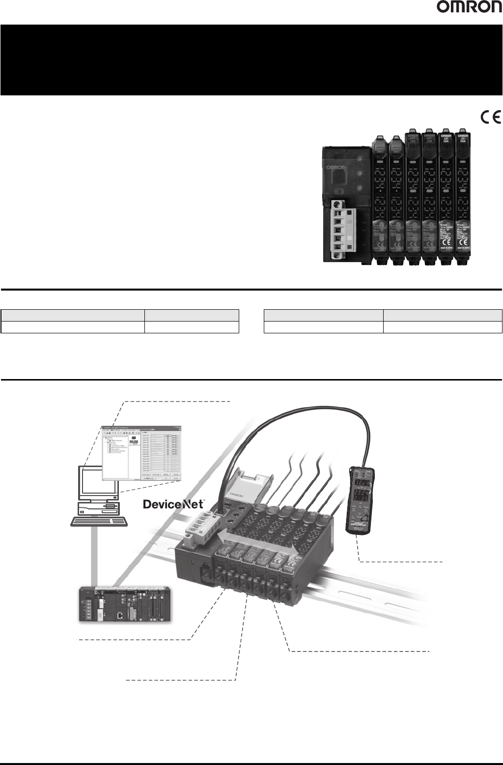
The DeviceNet Communication Unit That
Simplifies Managing Sensor Settings
• ON/OFF signals and incident light levels can be sent to the host PLC without
any need for programming (DeviceNet communications slave functionality).
• Threshold values and function settings can be read, written, or taught (using
the Message Communications function).
• Simply connect the communication cables and slide the Amplifiers from the
side for wire-saving.
• Up to 16 Sensor Amplifiers can be connected.
Ordering Information
● Digital Sensor Communications Unit ● Wire-saving Connector
Note: Order as many Connectors as the number of Sensors.
System Configuration
Name Model
Digital Sensor Communications Unit E3X-DRT21-S VER.3
Type Model
Cordless Slave Connector E3X-CN02
PLC
Configurator
Download a group of parameters for devices
(Sensors, Temperature Controllers, etc., supporting
DeviceNet) that you have prepared on your personal
computer in a single batch.
Monitor operating hours.
The operating hours for sensors can be stored
in internal memory and used for planning maintenance
and other applications.
Up to 16 channels can be
connected.
Supports a wide range of sensors.
The Unit supports a variety of digital sensors, including
Fiber Sensors, Laser Sensors, and Proximity Sensors.
Mobile Console
A built-in interface for a Mobile
Console lets you bring setting and
confirmation operations to your
fingertips.
Optical communications
Digital Sensor Communications Unit E3X-DRT21-S VER.3 93
Ratings and Specifications
Note 1: When any of the following Sensors is connected, two words are allocated per Sensor and each Sensor is counted as two Sensors for the number of connected Sensors.
E3X-DA@-S (@: 7/9), E3X-DA@TW-S (@: 6/8), E3X-MDA@ (@: 6/8), E3C-LDA@ (@: 6/8), E2C-EDA@ (@: 6/8)
E3X-DA@-S (@: 7/9), E3X-DA@TW-S (@: 6/8) have been discontinued at the end of March 2017.
2: Communications is possible for the ON/OFF output data from 13 Units. One word is allocated as the input area in the Master.
3: Communications is possible for the ON/OFF output data from 16 Units and the number of connected Sensors. Two words are allocated as the output area in the Master.
4: Communications is possible for the ON/OFF output data from 16 Units, the number of connected Sensors, and the detection levels for the connected Sensors.
Two words are allocated as the input area and one word is allocated for the number of connected Sensors in the Master.
5: Connection cannot be performed if the response speed of the Sensor is set to super-high-speed mode.
6: This does not include the current supplied to the Sensor.
7: E3X-DA-S Series and E3X-MDA Series are no longer available to order.
Dimensions
Item Description
Communications method DeviceNet communications
Communications
functions
Remote I/O
Communications Slave
function
Monitors ON/OFF output, status, incident light level (digital display data)
Message
Communications
function
Sets parameters using Explicit messages
Configurator Edits slave device parameters, enables device monitor functions
Mobile Console connection E3X-MC11-SV2 can be connected
Power supply
Supplied from the DeviceNet communications connector
(power is also supplied to all connected Sensors through Wire-reducing Connectors.)
Maximum connectable Sensors (See note 1.)
For remote I/O communications 1-CH mode (See note 2.) : 13
For remote I/O communications 2-CH mode (See note 3.) or
for remote I/O communications 2-CH mode + detection level monitoring mode (See note 4.) : 16
Connectable Sensors (See note 5.)
E3X-DA-S Series or E3X-MDA Series Digital Fiber Sensor (See note 7.)
E3C-LDA Series Laser Photoelectric Sensor with Separate Digital Amplifier
E2C-EDA High-resolution Digital Proximity Sensor with Separate Amplifier
(use connector-type Amplifier Units and the E3X-CN02 Cordless Slave Connector)
Power supply voltage 11 to 25 VDC
Current consumption (See note 6.) 70 mA max.
Ambient operating temperature -20°C to 55°C
Ambient operating humidity 35% to 85% (with no condensation)
Ambient storage temperature -30°C to 70°C
Dimensions (mm) 30 x 34.6 x71.3 (W x H x D)
Weight (packed state) Approx. 150 g
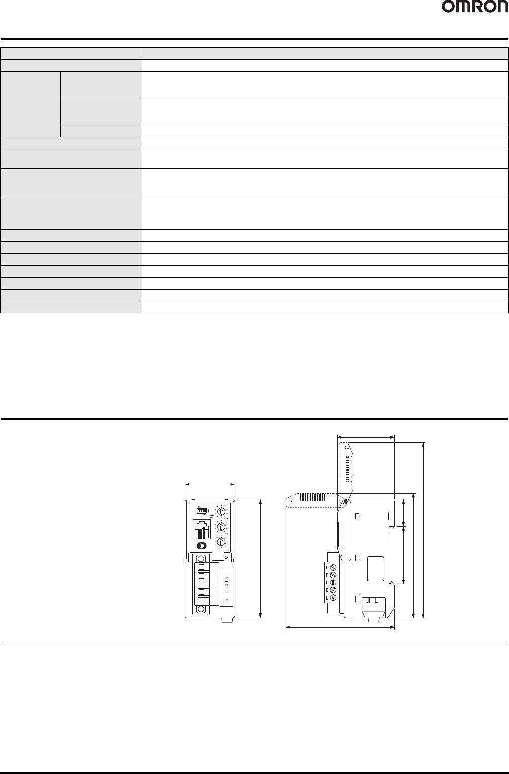
(Unit: mm)
Tolerance class IT16 applies to dimensions in this data sheet unless otherwise specified.
30
34.8
(75)
16
(106)
71.3
(65)
34.6
E3X-DRT21-S VER.3
94 DeviceNet ID Slave V600-HAM42-DRT
DeviceNet ID Slave
V600-HAM42-DRT
Electromagnetic-coupling ID System
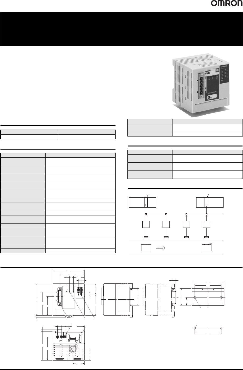
Conforms to DeviceNet and Saves
Wiring Effort
• The world's first Intelligent Flag III with support for DeviceNet.
• Responds flexibly to applications with data reading up to 24 bits.
• Switch writing between units of 8 bits and 16 bits.
• Address to access can be set from master.
Ordering Information
General Specifications
Performance Specifications
System Configuration
Dimensions (Unit: mm)
Name Model
Intelligent Flag III V600-HAM42-DRT
Item Model V600-HAM42-DRT
Communications power
supply voltage
11 to 25 VDC
Internal circuit power supply
voltage
18 to 26.4 VDC (24 VDC -25%/+10%)
Internal current
consumption current
Communications power supply: 40 mA max.
Internal circuitry power supply: 150 mA max.
Number of words allocated
to Master
Inputs: 2 words, Outputs: 2 words
Noise immunity
Internal circuitry power supply normal: ±600 V
Internal circuitry power supply common: ±1.5 kV
Vibration resistance 10 to 55 Hz, 1.5-mm double amplitude
Shock resistance
Malfunction: 200 m/s
2
Destruction: 300 m/s
2
Dielectric strength 500 VAC for 1 min between insulated circuits
Ambient operating
temperature
0°C to 55°C
Ambient operating humidity 35% to 85% (with no condensation)
Ambient operating
atmosphere
With no corrosive gas
Ambient storage
temperature
-25°C to 65°C
Dimensions 65 x 65 x 60 mm
Construction Panel-mounting
Mounting method
DIN track mounting or M4 screw mounting with
provided brackets.
Weight 150 g max.
Item Specifications
Number of sensor
connections
One channel
Applicable sensors
V600-HS51, V600-HS61,
V600-HS53, V600-HS67
Data Carrier communications
range
Read: 24 bits of data from the set address
Write: 16 bits of data from the set address
Item Model V600-HAM42-DRT
DeviceNet Master Unit DeviceNet Master Unit
Programmable
Controller
Programmable
Controller
V600-HAM42-DRT
Intelligent Flag III
V600-HS63 Sensor Unit
V600-D23P66
Data Carrier
Production
line
35.2
24.1
23.3
2.2
7.3
4.9
23.15.5
38.85
48.6
65
4
8
50.85
65
42.5
16 operation indicatorsThree operation
indicators
Connector
2.2×7=15.4
40.37.6
7.6
Three terminals
Connector
3
60
48
66
55
55
16.7
Two, 4.5-dia. mounting holes
2-M4
35
7.3
V600-HAM42-DRT
Mounting Hole Dimensions