drt2_devicenet_q102-e1_20_22_csm2147.pdf - 第134页
114 Safety Network Controller NE0A-SCPU01 Functions The follo wing function blocks are av ailable f or designing sa f ety circuits with the N E0A-SCPU01. These function bloc ks can be selected and assembled using the int…
Safety Network Controller NE0A-SCPU01 113
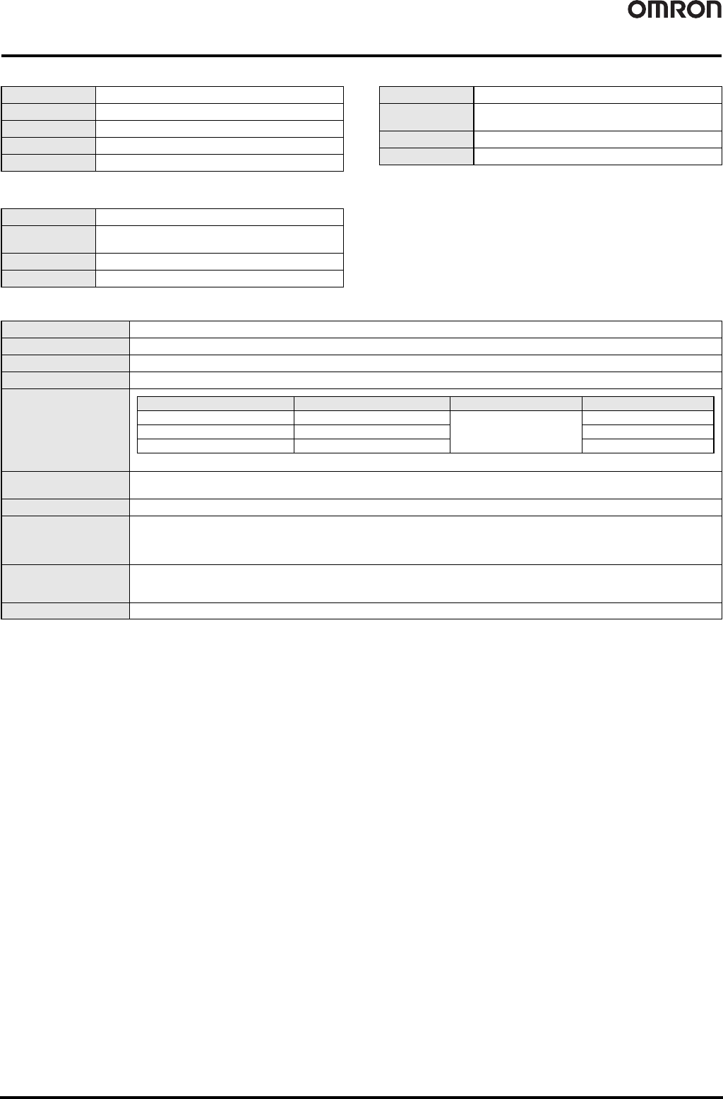
Safety Input Specifications
Safety Output Specifications
Test Output Specifications
DeviceNet Communications Specifications
Input type Sinking inputs (PNP)
ON voltage 11 VDC min. between each terminal and G1
OFF voltage 5 VDC min. between each terminal and G1
OFF current 1 mA max.
Input current 4.5 mA
Output type Sourcing outputs (PNP)
Rated output
current
0.5 A max./output
ON residual voltage 1.2 V max. between each output terminal and V2
Leakage current 0.1 mA max.
Output type Sourcing outputs (PNP)
Rated output
current
60 mA
ON residual voltage 1.2 V max. between each output terminal and V1
Leakage current 0.1 mA max.
Communications protocol Conforms to DeviceNet
Connection form Multi-drop system and T-branch system can be combined (for trunk line and branch lines)
Baud rate 500/250/125 kbps
Communications media Special cable, 5 conductors (2 for communications, 2 for power supply, 1 for shielding)
Communications distance
Communications power
supply
11 to 25 VDC
Maximum number of nodes 63
Safety I/O communications
Safety Master function
• Max. no. of connections: 2 (one each for inputs and outputs)
Multi-cast inputs can be used to enable communications with up to 15 Safety Masters.
• Connection type: Single-cast, multi-cast
Standard I/O
communications
Standard Slave function
• Max. no. of connections: 2
• Connection type: Poll, bit-strobe, COS, cyclic
Message communications Max. message length: 502 bytes
The values in parentheses are for Thin Cable.
Baud rate Network length (max.) Branch line length Total branch line length
500 kbps 100 m max. (100 m max.)
6 m max.
39 m max.
250 kbps 250 m max. (100 m max.) 78 m max.
125 kbps 500 m max. (100 m max.) 156 m max.
114 Safety Network Controller NE0A-SCPU01
Functions
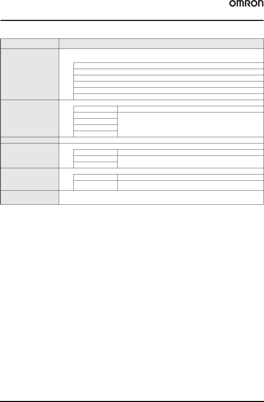
The following function blocks are available for designing safety circuits with the NE0A-SCPU01.
These function blocks can be selected and assembled using the interactive wizard format to efficiently design safety applications.
Note: There is a possibility that safety cannot be maintained when an OR part or an AND/OR part is selected for input logic, or an OR/AND part is selected for output logic. Sufficiently
confirm safety prior to use.
Classification of function block
for safety circuit designs
Application
Function blocks for safety input
devices and setting input filter
times
The following six parts can be selected for use as safety input devices.
For Category 3 or 4 compliance, the filter monitoring time between signals can also be adjusted with redundant wiring for the necessary
safety devices.
Emergency Stop Switches
Safety Door Switches
Limit Switches
Safety Light Curtains
Enabling Switches
Mode Selectors
Logic function blocks for input
conditions
Select a Safety Light Curtain as the safety input device, and select a muting function when required.
No setting Uses the ON/OFF status from the safety input device exactly as it is.
OR operation
• For switching maintenance areas with a Mode Selector.
• For applications such as a Safety Light Curtain muting function.
AND/OR operations
AND operation
OR/AND operations
Function blocks for resets Selects manual or auto reset.
Logic function blocks for output
conditions
For applications such as stopping all outputs for multiple safety devices.
No setting Uses the ON/OFF status of the safety signal exactly as it is.
AND operation
Selects the interlock conditions for the safety signal.
OR/AND operations
Function blocks for setting the
welded contact check
Used to check the safety condition of an output device.
No setting No checking of the output device (used for Category 2 or lower).
EDM
Used to check for contact welding in a Relay or Contactor.
Also used to change the setting for monitoring time.
Function blocks for safety output
devices and setting output delay
times
For setting an auxiliary output (to output an error condition) and for setting the output delay.
Safety Network Controller NE0A-SCPU01 115
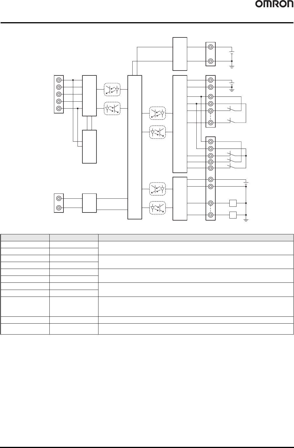
Internal Circuit Diagrams
NE0A-SCPU01
Terminal No. Terminal name Description
-- V0
Power supply terminal for internal circuit (24 VDC)
-- G0
1V1
Power supply terminal for external input device and test output (24 VDC)
11 G1
24 V2
Power supply terminal for external output device (24 VDC)
34 G2
2 to 10 IN0 to IN8
Safety input terminal
Terminals IN10 and IN11 are used only for connecting a reset switch or EDM feedback.
21 to 23 IN9 to IN11
12 to 20
31 to 33
T0 to T1
Test output terminal
Connected to IN0 to IN11 safety inputs.
T0 and T1 output test pulses with different patterns.
The T0 terminals are internally connected and the T1 terminals are internally connected.
25 to 30 OUT0 to OUT5 Safety output terminals
35 to 40 G2
Common terminal
Terminals 34 to 40 are internally connected.
24 VDC
V0
G0
V1
G1
T0
T1
IN0
IN8
T0
T1
IN9
IN10
IN11
V2
G2
OUT0
L
L
OUT5
24 VDC
24 VDC
D+
D-
V+
CAN H
Shield
CAN L
V-
DeviceNet
Physical Layer
DC-DC Converter
(Non-insulated)
Internal Circuit
USB
DC-DC Converter
(Non-insulated)
Safety Input Circuit
Test Output Circuit
Safety Output Circuit