drt2_devicenet_q102-e1_20_22_csm2147.pdf - 第139页
Safety Network Controller NE1A-SCPU Series 119 Internal Circ uit Diagrams V+ CAN H DRAIN CAN L V- D+ D- DeviceNet Physical La yer DC-DC Converter (Non-insulated) DC-DC Converter (Insulated) Safety Input Circuit T est Out…
118 Safety Network Controller NE1A-SCPU Series
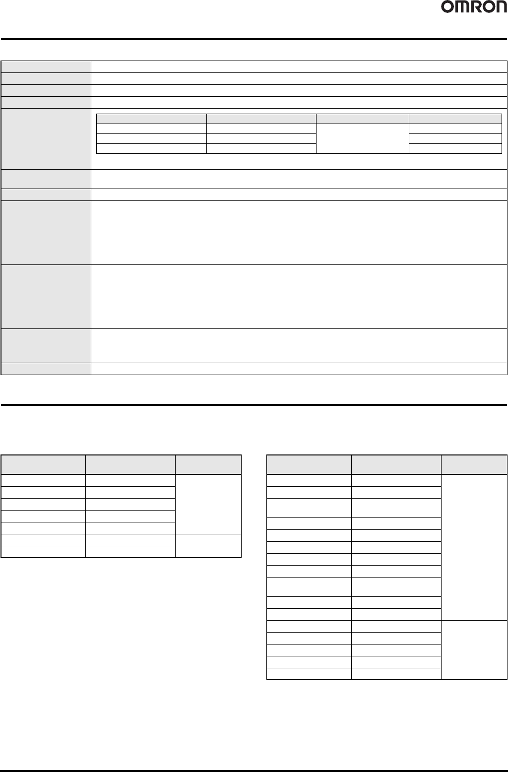
DeviceNet Communications Specifications
Functions
Function Blocks
NE1A-SCPU-series Controller support the following logic functions and function blocks. Support depends on the unit version.
● Logic Functions ● Function Blocks
Communications protocol Conforms to DeviceNet
Connection form Multi-drop system and T-branch system can be combined (for trunk line and branch lines)
Baud rate 500/250/125 kbps
Communications media Special 5-wire cable (2 signal lines, 2 power supply lines, 1 shield line)
Communications distance
Communications power
supply
11 to 25 VDC
Maximum number of nodes 63
Safety I/O communications
(Pre-Ver. 1.0)
Safety Master function
• Max. no. of connections: 16
• Max. data size: Input 16 bytes or output 16 bytes (per connection)
• Connection type: Single-cast, multi-cast
Safety Slave function
• Max. no. of connections: 4
• Max. data size: Input 16 bytes or output 16 bytes (per connection)
• Connection type: Single-cast, multi-cast
Safety I/O communications
(unit version 1.0 or later)
Safety Master function
• Max. no. of connections: 32
• Max. data size: Input 16 bytes or output 16 bytes (per connection)
• Connection type: Single-cast, multi-cast
Safety Slave function
• Max. no. of connections: 4
• Max. data size: Input 16 bytes or output 16 bytes (per connection)
• Connection type: Single-cast, multi-cast
Standard I/O
communications
(all unit versions)
Standard Slave function
• Max. no. of connections: 2
• Max. data size: Input 16 bytes or output 16 bytes (per connection)
• Connection type: Poll, bit-strobe, COS, cyclic
Message communications Max. message length: 552 bytes
The values in parentheses are for Thin Cable.
Baud rate Network length (max.) Branch line length Total branch line length
500 kbps 100 m max. (100 m max.)
6 m max.
39 m max.
250 kbps 250 m max. (100 m max.) 78 m max.
125 kbps 500 m max. (100 m max.) 156 m max.
Name Function list entry
Supporting unit
versions
NOT
NOT
All
AND
AND
OR
OR
Exclusive OR
EXOR
Exclusive NOR
EXNOR
RS Flip-flop
RS-FF
1.0 or later
Comparator
Comparator
Name Function list entry
Supporting unit
versions
Reset
Reset
All
Restart
Restart
Emergency Stop
Monitoring
E-STOP
Light Curtain Monitoring
Light Curtain Monitoring
Safety Gate Monitoring
Safety Gate Monitoring
Two-hand Controller
Two Hand Controller
Off-Delay Timer
Off-Delay Timer
On-Delay Timer
On-Delay Timer
User Mode Switch
Monitoring
User Mode Switch
External Device Monitoring
EDM
Routing
Routing
Muting
Muting
1.0 or later
Enable Switch Monitoring
Enable Switch
Pulse Generator
Pulse Generator
Counter
Counter
Multiconnector
Multi Connector
Safety Network Controller NE1A-SCPU Series 119
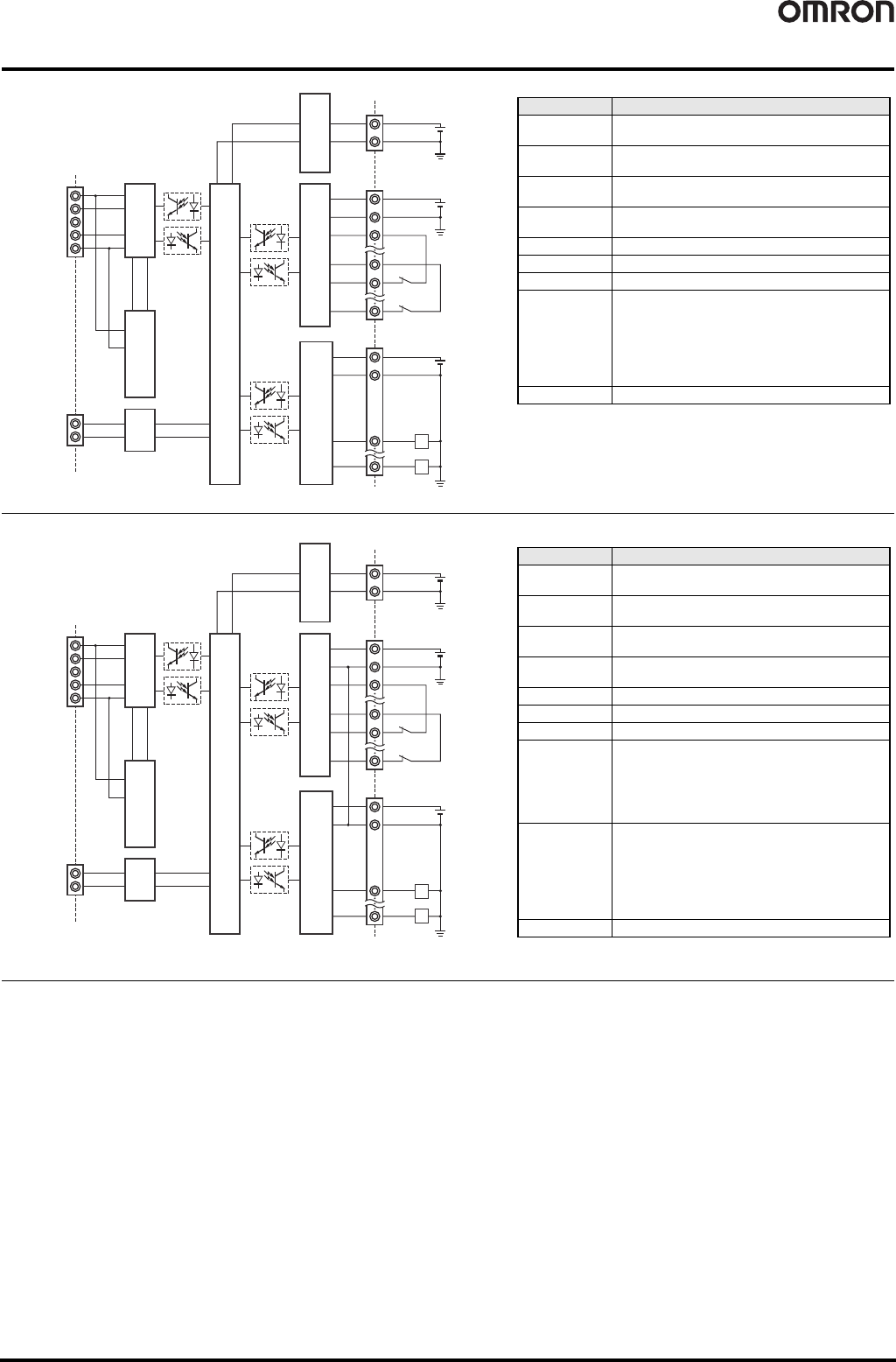
Internal Circuit Diagrams
V+
CAN H
DRAIN
CAN L
V-
D+
D-
DeviceNet
Physical Layer
DC-DC Converter
(Non-insulated)
DC-DC Converter
(Insulated)
Safety Input Circuit
Test Output Circuit
Internal Circuit
USB
24 VDC
24 VDC
V0
G0
V1
G1
T0
T3
IN0
IN15
Safety Output Circuit
24 VDC
V2
G2
L
OUT0
L
OUT7
Terminal name Description
V0
Power supply terminal for internal circuit
The two V0 terminals are internally connected.
G0
Power supply terminal for internal circuit
The two G0 terminals are internally connected.
V1
Power supply terminal for external input device and
test output
G1
Power supply terminal for external input device and
test output
V2
Power supply terminal for external output device
G2
Power supply terminal for external output device
IN0 to IN15 Safety input terminal
T0 to T3
Test output terminal
Connected to IN0 to IN15 safety inputs.
Each test output terminal outputs a different test
pulse pattern.
Terminal T3 also supports a current monitoring
function for the output signal.
Example: Muting lamp
OUT0 to OUT7 Safety output terminals
NE1A-SCPU01-V1
V+
CAN H
DRAIN
CAN L
V-
D+
D-
DeviceNet
Physical Layer
DC-DC Converter
(Non-insulated)
DC-DC Converter
(Insulated)
Safety Input Circuit
Test Output Circuit
Internal Circuit
USB
24 VDC
24 VDC
V0
G0
V1
G
T0
T7
IN0
IN39
Safety Output Circuit
24 VDC
V2
G
L
OUT0
L
OUT7
Terminal name Description
V0
Power supply terminal for internal circuit
The two V0 terminals are internally connected.
G0
Power supply terminal for internal circuit
The two G0 terminals are internally connected.
V1
Power supply terminal for external input device and
test output
G
Power supply terminal for external input device and
test output
V2
Power supply terminal for external output device
G
Power supply terminal for external output device
IN0 to IN39 Safety input terminal
T0 to T3
Connected to IN0 to IN19 safety inputs.
Each test output terminal outputs a different test
pulse pattern.
Terminal T3 also supports a current monitoring
function for the output signal.
Example: Muting lamp
T4 to T7
Test output terminal
Connected to IN20 to IN39 safety inputs.
Each test output terminal outputs a different test
pulse pattern.
Terminal T7 also supports a current monitoring
function for the output signal.
Example: Muting lamp
OUT0 to OUT7 Safety output terminals
NE1A-SCPU02
120 Safety Network Controller NE1A-SCPU Series
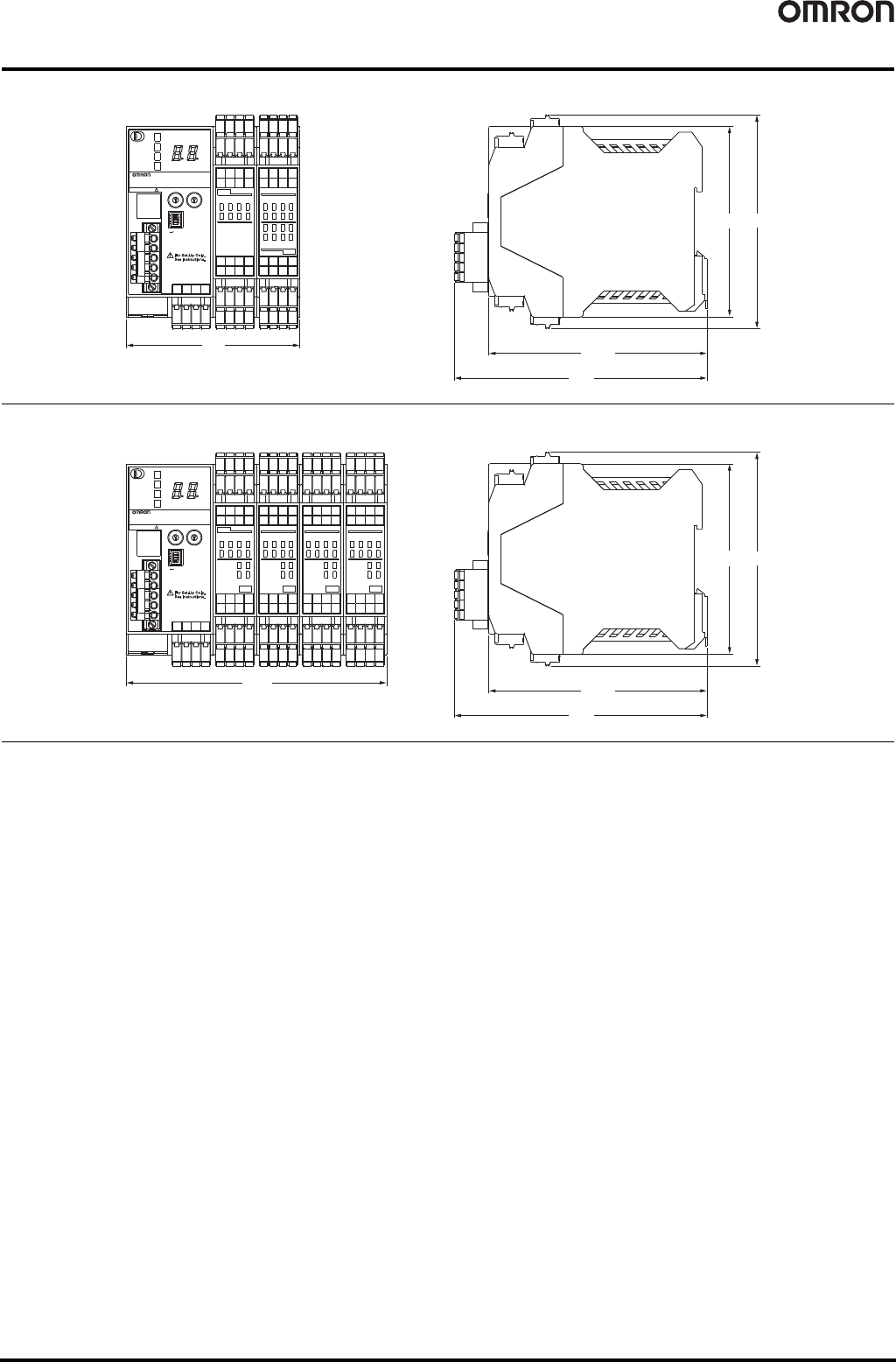
Dimensions (Unit: mm)
NE1A-SCPU01-V1
NE1A-SCPU02
90.4
(99) 111.1
24VDC
×10 ×1
ON
1
0
1
0
3
2
5
4
7
6
1
0
3
2
5
4
7
6
1
0
3
2
5
4
7
6
9
8
11
10
13
12
15
14
3
2
5
4
7
6
9
8
11
10
13
12
15
14
SAFETY NETWORK CONTROLLER
00
USB
NS
MS
LOCK
COMM
NE1A-SCPU01-V1
NODE ADR
BAUD RATE
V0 G0
24VDC
OUT
IN
V1 G1
V2 G2
T0 T2
T1 T3
V1 G1
V2 G2
T0 T2
T1 T3
V0 G0
1
2
3
4
O
N
(114.1)
131.4
135.6
(99) 111.1
24VDC
×10 ×1
ON
1
0
1
0
3
2
5
4
7
6
1
0
3
2
17
16
19
18
T1
T0
T3
T2
1
0
3
2
17
16
19
18
9
8
11
10
13
12
15
14
3
2
5
4
7
6
9
8
11
10
13
12
15
14
SAFETY NETWORK CONTROLLER
00
USB
NS
MS
LOCK
COMM
NE1A-SCPU02
NODE ADR
BAUD RATE
V0 G0
24VDC
OUTIN
37
36
39
38
IN
IN
V1 G
V2 G
21
20
21
20
23
22
25
24
27
26
5
4
7
6
T5
T4
T7
T6
5
4
7
6
29
28
31
30
33
32
35
34
23
22
25
24
27
26
29
28
31
30
33
32
35
34
OUT
NC NC
NC NC
36 38
37 39
V0 G0
1
2
3
4
O
N
(114.1)
131.4