drt2_devicenet_q102-e1_20_22_csm2147.pdf - 第141页
Safety Network Controller NE1A-SCPU Series 121 Safety Precautions ● Be sure to re ad the follo wing operation manual f or precauti ons and other details required for correct use of the Safety Network Contr oller . CIP Sa…
120 Safety Network Controller NE1A-SCPU Series
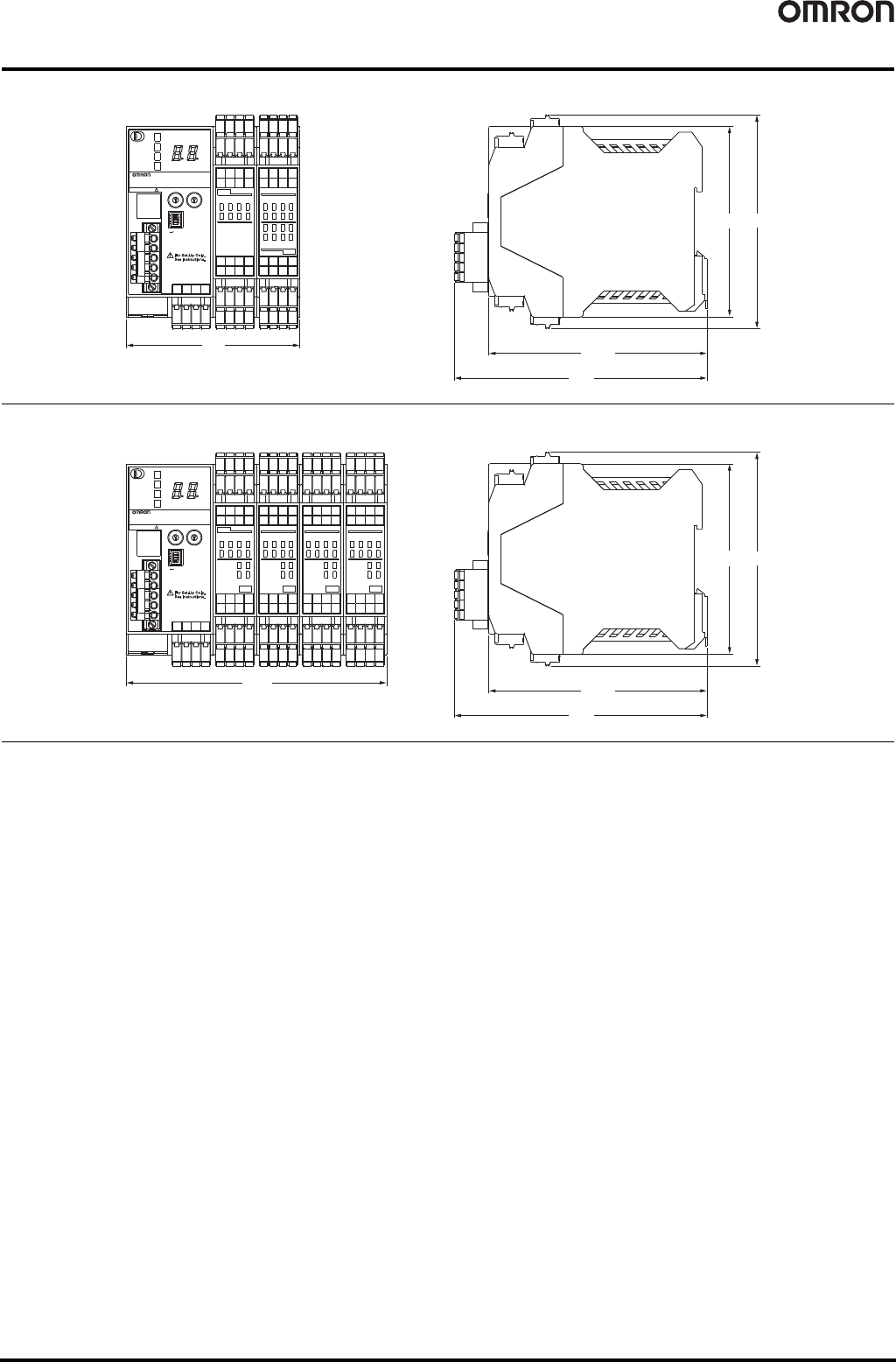
Dimensions (Unit: mm)
NE1A-SCPU01-V1
NE1A-SCPU02
90.4
(99) 111.1
24VDC
×10 ×1
ON
1
0
1
0
3
2
5
4
7
6
1
0
3
2
5
4
7
6
1
0
3
2
5
4
7
6
9
8
11
10
13
12
15
14
3
2
5
4
7
6
9
8
11
10
13
12
15
14
SAFETY NETWORK CONTROLLER
00
USB
NS
MS
LOCK
COMM
NE1A-SCPU01-V1
NODE ADR
BAUD RATE
V0 G0
24VDC
OUT
IN
V1 G1
V2 G2
T0 T2
T1 T3
V1 G1
V2 G2
T0 T2
T1 T3
V0 G0
1
2
3
4
O
N
(114.1)
131.4
135.6
(99) 111.1
24VDC
×10 ×1
ON
1
0
1
0
3
2
5
4
7
6
1
0
3
2
17
16
19
18
T1
T0
T3
T2
1
0
3
2
17
16
19
18
9
8
11
10
13
12
15
14
3
2
5
4
7
6
9
8
11
10
13
12
15
14
SAFETY NETWORK CONTROLLER
00
USB
NS
MS
LOCK
COMM
NE1A-SCPU02
NODE ADR
BAUD RATE
V0 G0
24VDC
OUTIN
37
36
39
38
IN
IN
V1 G
V2 G
21
20
21
20
23
22
25
24
27
26
5
4
7
6
T5
T4
T7
T6
5
4
7
6
29
28
31
30
33
32
35
34
23
22
25
24
27
26
29
28
31
30
33
32
35
34
OUT
NC NC
NC NC
36 38
37 39
V0 G0
1
2
3
4
O
N
(114.1)
131.4
Safety Network Controller NE1A-SCPU Series 121
Safety Precautions
● Be sure to read the following operation manual for precautions and other details required for correct use of the Safety
Network Controller. CIP Safety on DeviceNet Safety Network Controller Operation Manual (Cat. No. Z906)
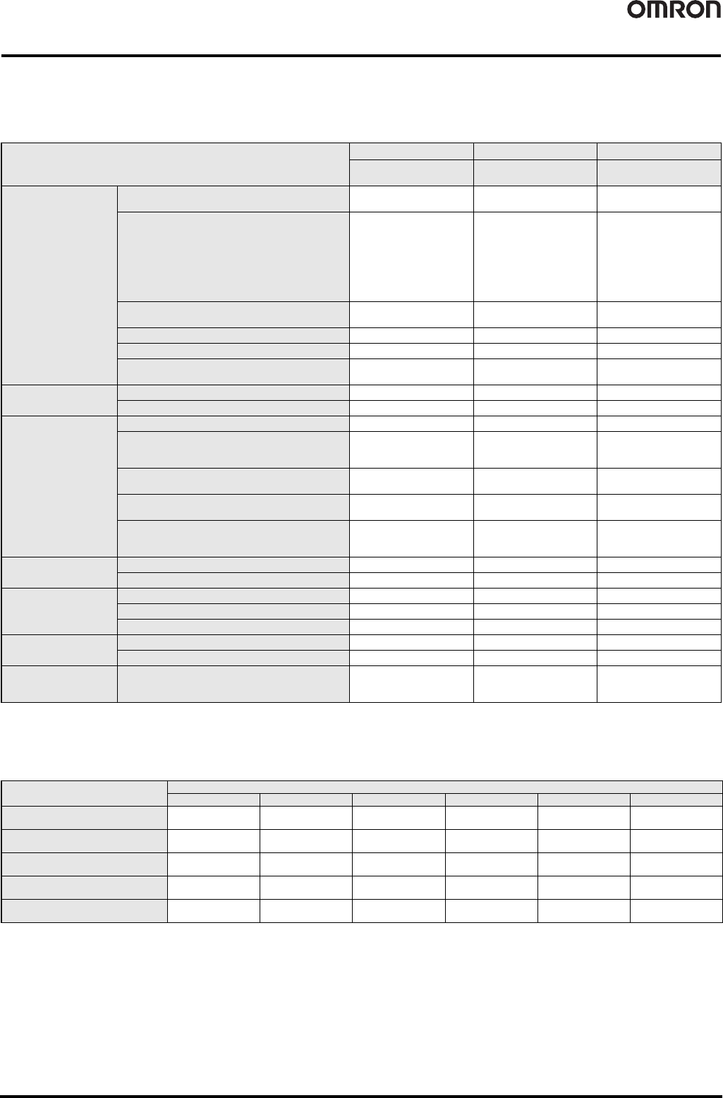
Functions Supported According to Unit Version
❍ : Supported, ---: Not supported
● Unit Versions and Network Configurator Versions
Network Configurator version 2.0@ or higher must be used when using a NE1A-SCPU01-V1 or NE1A-SCPU02 Safety Logic Controller with unit
version 2.0.
❍ : Supported, ---: Not supported
*1. It can be used as unit version 1.0.
Note 1: Users who use Network Configurator version 1.5@ or earlier can upgrade to version 1.6@ at no charge.
Note 2: When using Network Configurator version 1.6@, there are no operational differences in the NE1A-SCPU01-V1 and NE1A-SCPU02.
● Version Upgrade
If you have purchased Ver.1.@@, you will need to buy the upgrade CD-ROM. (Refer to page 127.)
Model NE1A-SCPU01 NE1A-SCPU01-V1 NE1A-SCPU02
Function Unit version Pre-Ver. 1.0
Unit version
1.0/2.0
Unit version
1.0/2.0
Logic processing
functions
Maximum program size
(total number of function blocks)
128 254 254
New Function Blocks
• RS flip-flop
• Multiconnector
•Muting
• Enable Switch Monitoring
• Pulse Generator
• Counter
•Comparator
--- ❍❍
Selecting a rising edge as the reset condition for
Reset and Restart function blocks
--- ❍❍
Using local I/O status in logic programming --- ❍❍
Using overall Unit status in logic programming --- ❍❍
Program execution wait functions ---
❍
(Unit version 2.0 or higher)
❍
(Unit version 2.0 or higher)
I/O control functions
Monitoring contact operation counter --- ❍❍
Mounting total ON time monitor --- ❍❍
DeviceNet
communications
functions
Number of safety I/O connections for Safety Master 16 32 32
Selecting operating mode for safety I/O
communications when communications errors
occur
--- ❍❍
Attaching local output data to send data during
slave operation
--- ❍❍
Attaching local I/O monitor data to send data during
slave operation
--- ❍❍
Functions to communicate with devices existing on
other networks
(Off-Link connection)
---
❍
(Unit version 2.0 or higher)
❍
(Unit version 2.0 or higher)
System startup and error
recovery functions
Storing log of nonfatal errors in nonvolatile memory --- ❍❍
Adding function block errors to error log --- ❍❍
EtherNet/IP
communications
functions
I/O communications --- --- ---
Message communications --- --- ---
Read/write of target I/O area --- --- ---
Routing between
DeviceNet and EtherNet/IP
I/O routing --- --- ---
Message routing --- --- ---
UDP/IP message
communications
functions
Message communications by UDP/IP --- --- ---
Model
Network Configurator
Ver. 1.3@ Ver. 1.5@ Ver. 1.6@ Ver. 2.0@/2.1@ Ver.2.2@ Ver.3.3@
NE1A-SCPU01
Pre-Ver. 1.0
❍❍❍❍❍❍
NE1A-SCPU01-V1
Unit version 1.0
✕ ✕❍❍❍❍
NE1A-SCPU02
Unit version 1.0
✕ ✕❍❍❍❍
NE1A-SCPU01-V1
Unit version 2.0
✕✕ ❍ (*1) ❍❍❍
NE1A-SCPU02
Unit version 2.0
✕✕ ❍ (*1) ❍❍❍
122 Safety I/O Terminals DST1 Series
Safety I/O Terminals
DST1 Series
Distributed Safety Terminals
That Reduce Wiring.
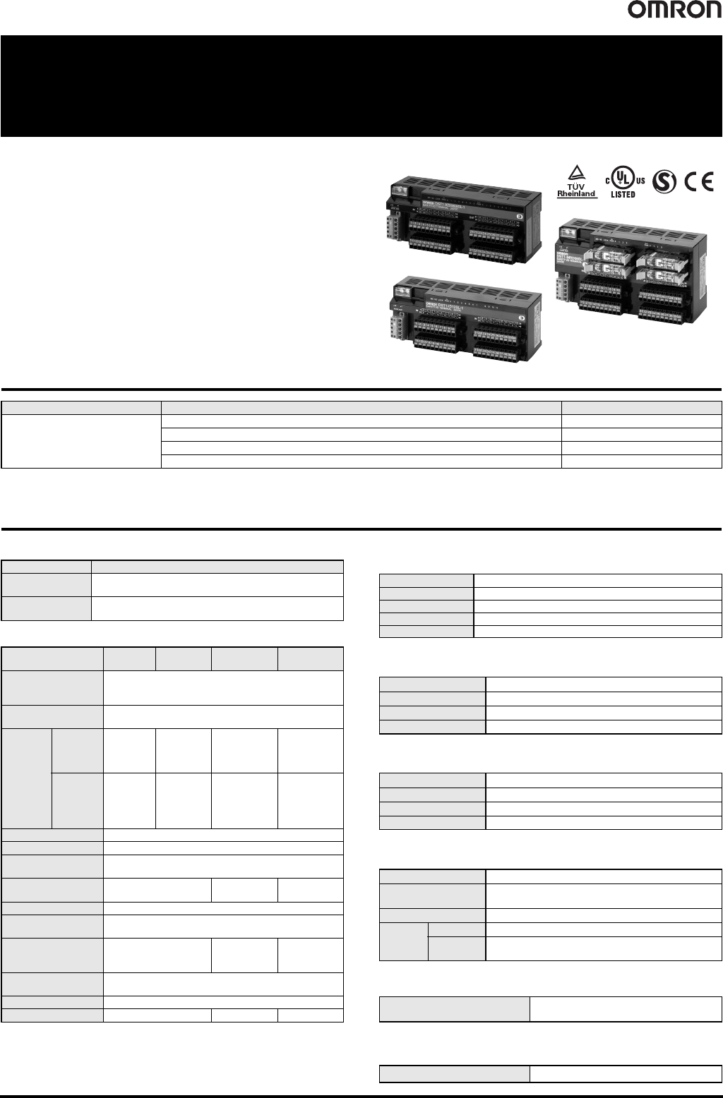
• Lineup includes four models to accommodate various
I/O types and number of I/O points.
• Monitor the safety system from Standard Controllers
across the network.
• EN954-1 (Cat.4), ISO13849-1 (PLe), and
IEC 61508 SIL3 certification.
• The DST1-XD0808SL-1 also supports logic operation
functions for high-speed processing in applications
requiring partial stopping of the safety system.
Ordering Information
Note: The standard DS1T Safety I/O Terminals are equipped with spring-cage terminal blocks, but screw terminal blocks are available if desired, e.g., to replace previous terminals.
Refer to CIP Safety on DeviceNet Accessories.
* Use the Safety Network Configurator Ver. 2.0 or later to make DST1-XD0808SL-1 settings.
Specifications
Certified Standards
General Specifications
* Not including power consumption for external devices.
Safety Input Specifications
(Common with the DST1 Series)
Safety Output Specifications (Semiconductor
output)
(Common with the DST1-MD16SL-1/XD0808SL-1)
Test Output Specifications
(Common with the DST1 Series)
Safety Output Specifications (Relay Output)
(DST1-MRD08SL-1)
* This value is equivalent to 300 operations/minute.
CIP Safety on DeviceNet Communications
DeviceNet Slave Communications
(Common with the DST1 Series)
Name I/O points Model
Safety I/O Terminals
Safety inputs: 12, test outputs: 4 DST1-ID12SL-1
Safety inputs: 8, safety outputs (semiconductor): 8, test outputs: 4 DST1-MD16SL-1
Safety inputs: 8, safety outputs (semiconductor): 8, test outputs: 4 DST1-XD0808SL-1 *
Safety inputs: 4, safety outputs (relay): 4, test outputs: 4 DST1-MRD08SL-1
Certification body Standard
TÜV Rheinland
EN ISO 13849-1, EN ISO 13849-2, IEC 61508, EN 62061,
EN 61131-2, IEC 61326-3-1
UL
UL508, ISA12.12.01 (excluding the DST1-MRD08SL-1),
UL1998, IEC 61508-3
Item
Model DST1-
ID12SL-1
DST1-
MD16SL-1
DST1-
MRD08SL-1
DST1-
XD0808SL-1
DeviceNet
Communications
power supply voltage
11 to 25 VDC
(supplied from the communications connector)
I/O power supply
voltage
20.4 to 26.4 VDC (24 VDC -15%/+10%)
Current
con-
sumption
Commu-
nications
power
supply
24 VDC,
100 mA
24 VDC,
110 mA
24 VDC,
100 mA
24 VDC,
110 mA
I/O power
supply *
24 VDC
70 mA
24 VDC
50 mA
(Input)
130 mA
(Output)
24 VDC
80 mA
(Input)
130 mA
(Output)
24 VDC
50 mA
(Input)
130 mA
(Output)
Overvoltage category II
Noise immunity Conforms to IEC61131-2
Vibration resistance
10 to 57 Hz: 0.35-mm single amplitude,
57 to 150 Hz: 50 m/s
2
Shock resistance
150m/s
2
11ms
100m/s
2
11ms
150m/s
2
11ms
Mounting method DIN track mounting (DIN 35 mm)
Ambient operating
temperature
-10°C to 55°C
Ambient operating
humidity
10% to 95%
(with no condensation)
10% to 85%
(with no
condensation)
10% to 95%
(with no
condensation)
Ambient storage
temperature
-40°C to 70°C
Degree of protection IP20
Weight 420 g 600 g 420 g
Input type Sinking inputs (PNP)
ON voltage 11 VDC min.
OFF voltage 5 VDC max.
OFF current 1 mA max.
Input current 6 mA
Output type Sourcing outputs (PNP)
Rated output current 0.5 A max./output
ON residual voltage 1.2 V max.
Leakage current 0.1 mA max.
Output type Sourcing outputs (PNP)
Rated output current 0.7 A max./output
ON residual voltage 1.2 V max.
Leakage current 0.1 mA max.
Applicable relays G7SA-2A2B, EN50205 Class A
Failure rate P level *
(Reference value)
5 VDC, 1 mA
Rated load (resistive) 2 A at 240 VAC, 2 A at 30 VDC
Durability
Mechanical 5,000,000 operations min. (at 7,200 operations/h)
Electrical
100,000 operations min. (at 1,800 operations/h with a
resistive load)
Safety Slave communications
Max. 4 connections (Max. 2 connections for
the DST1-XD0808SL-1)
Standard Slave communications Max. 2 connections