drt2_devicenet_q102-e1_20_22_csm2147.pdf - 第86页
66 SmartSlice GRT1-series Set Only the Node Ad dresses Automatic baud r ate detection and automatic I/O allocations enable immediate use with no Suppor t Software. Reco ver Unit P arameters without Suppor t Software Unit…
SmartSlice GRT1 Series 65
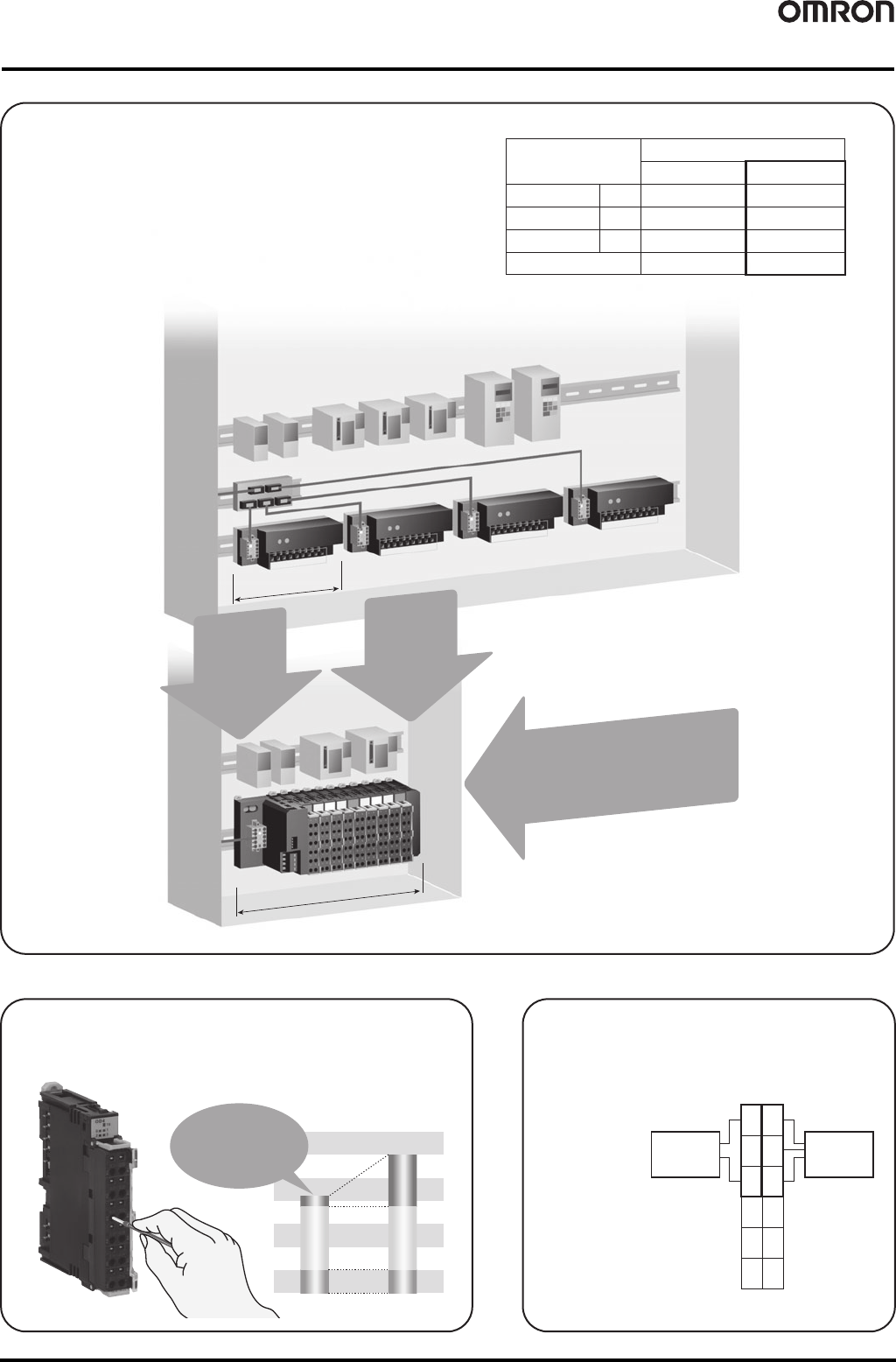
Easily save space and
reduce costs.
Required number
of points
Inputs
Outputs
Analog inputs
20
10
2
12
6
2
4
0
2
0
1
Number of redundant points
Previous slaves SmartSlice
Reduce
work.
Decrease the number of
nodes and reduce
wiring work.
Cut
costs.
Approximately
85
%
Save space.
Approximately
1/2
the width.
115 mm
213 mm
Number of nodes
Also Save Space in
the Control Panel
One-touch Wiring
The terminal block with screwless clamp terminals greatly reduces work. Also,
additional tightening is not required because vibration does not cause
loosening.
V and G
terminals are provided
for each input signal.
Relay terminals are no
longer required, which
helps save space in the
control panel.
Three-wire
sensor
(Photoelectric
sensor, etc.)
Two-wire
sensor
(Proximity sensor,
limit switch, etc.)
1
V
G
3
V
G
0
V
G
2
V
G
Reduction in
Work Time
Actual wiring: 1/5
Total: 2/3
Work Time Comparison
Wire stripping
Crimping
Actual wiring
Terminal
Arrangement
66 SmartSlice GRT1-series
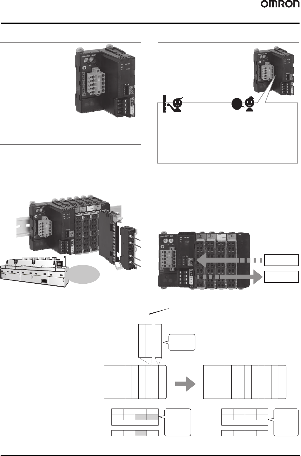
Set Only the Node Addresses
Automatic baud rate detection
and automatic I/O allocations
enable immediate use with no
Support Software.
Recover Unit Parameters
without Support Software
Unit data can be backed up by manipulating a DIP switch.
Automatically restoring data after Unit replacement improves
maintenance efficiency.
Equipped with Smart Functions
The Slave Unit stores the
equipment operating time and
amount of change in operation as
data to enable monitoring without
increasing the load between
Controllers.
The number of ON/OFF
operations of the equipment and
the total operating time are
counted by the Slave Unit to
provide notification when
maintenance is required.
Smart Timing Smart Counting
The highly acclaimed Smart Functions
of the DRT2 Series are used.
This helps monitor the operation status
of the equipment and improves
capacity utilization.
1, 2, 3,
4, 5...
Ideal for
applications such
as furnaces
Backup
Restore
I/O Allocation Software Settings
● This function enables registering the I/O
configuration data of a non-mounted SmartSlice
I/O Unit as a dummy.
● Securing the required capacity for expansion
in the I/O map in advance when I/O Units
must be added in the future prevents
discrepancies in the I/O map when actual
expansion is performed and eliminates the
need for significant changes in programming.
SmartSlice
I/O Units to be
added later
Add the Units
DeviceNet
Communications
Unit
#
1
#
5
#
6
#
8
4 inputs
4 inputs4 inputs
4 inputs
4 inputs
4 inputs
4 inputs
4 inputs
4 inputs
4 inputs
4 inputs
4 inputs
4 outputs
4 outputs
4 outputs
4 outputs
#
2
#
3
#
4
#
7
End Unit
End Unit
#
1
#
2
#
3
#
4
#
7
#
6
#
5
#
8
Registered as
a Dummy Unit.
The bits for
planned
expansion
secured in
advance.
(Shaded Area)
No
discrepancies
occur in the
I/O map when
expansion
is performed.
Bit 15 8 Bit 0
Input Area +0ch
+1ch
+2ch
Output Area +0ch
#4 #3 #2 #1
#5#6
Next node
#7#8
Bit 15 8 Bit 0
Input Area +0ch
+1ch
+2ch
Output Area +0ch
#4 #3 #2 #1
#5#6
Next node
#7#8
DeviceNet
Communications
Unit
Online replacement makes
maintenance easy
The terminal block, main block, and power supply block of the
I/O Unit are detachable.
Replacement can be performed online without changing the I/O wiring
and while maintaining communications for the remaining Units.
This is ideal for applications such as furnaces, where heaters must be
remain turned ON as much as possible.
New Function
SmartSlice GRT1 Series 67
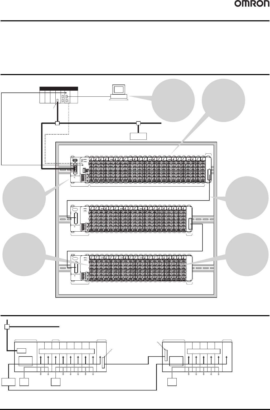
Support for flexible I/O configurations to match the application
help downsize the control panel, cut costs, and decrease wiring
work.
System Configuration
Internal Circuit Configuration
DeviceNet
CX-One
PLC
ID4
GRT1-DRT
TS
10
2
1
3
0
2
1
3
0
2
1
3
0
2
1
3
0
2
0
1
0
1
TS TS TS TS TS TS
ID4 OD4 OD4 PD2 ID4 ROS2 ROS2
ID4
TS
1
3
0
2
1
3
0
2
1
3
0
2
1
3
0
2
1
3
0
2
TS TS TS TS
1
3
0
2
TS
ID4 ID4 OD4 OD4 OD4
ID4
TS
1
3
0
2
1
3
0
2
1
3
0
2
1
3
0
2
1
3
0
2
TS TS TS TS
1
3
0
2
TS
ID4 ID4 OD4 OD4 OD4 END
1
3
0
2
0
1
0
1
TS TS TS
PD2 ID4 ROS2 ROS2
1
3
0
2
0
1
0
1
TS TS TS
PD2 ID4 ROS2 ROS2
1
3
0
2
0
1
0
1
TS TS TS
PD2 ID4 ROS2 ROS2
1
3
0
2
0
1
0
1
TS TS TS
PD2 ID4 ROS2 ROS2
1
3
0
2
0
1
0
1
TS TS TS
PD2 ID4 ROS2 ROS2
1
3
0
2
0
1
0
1
TS TS TS
PD2 ID4 ROS2 ROS2
0
1
0
1
TS TS
ROS2 ROS2
1
3
0
2
0
1
0
1
TS TS TS
PD2 ID4 ROS2 ROS2
1
3
0
2
0
1
0
1
TS TS TS
PD2 ID4 ROS2 ROS2
1
3
0
2
0
1
0
1
TS TS TS
PD2 ID4 ROS2 ROS2
0
1
0
1
TS TS
ROS2 ROS2
1
3
0
2
0
1
0
1
TS TS TS
PD2 ID4 ROS2 ROS2
GRT1-TBL
GRT1-TBL
TBR
TBR
INX
OUTX
WORD
NODE ADR
[0-63]
BS |
BS {
BD H
BD L
DC24V
INPUT
Serial connection
(Settings, monitoring,
operation)
CS/CJ-series
DeviceNet
Master Unit
Up to 64 I/O Units can be connected
to a DeviceNet Communications Unit.
* The End Unit is sold separately.
An End Unit is required at the end.
Turnback Cable (1 m)
GCN2-100
Turnback Cable (1 m)
GCN2-100
End Unit
GRT1-END
DeviceNet
Communications Unit
GRT1-DRT
Slice I/O Unit
Right Turnback Unit
GRT1-TBR
Right Turnback
Unit
GRT1-TBR
Left Turnback Unit
GRT1-TBL
Left Turnback Unit
GRT1-TBL
Slave
*
Flexibility is
provided in the
combinations for the
number of I/O points. It is
possible to mix a variety
of Units, such as Input
Units and Output Units as
well as Analog Units
and Digital Units.
Wiring is easy. Simply
insert the ferrule.
(No screwdriver is
required.)
A DeviceNet
Communications Unit
is featured in the
product lineup.
Parameters can be
set and maintenance
performed for
Communications Units or
SmartSlice I/O Units.
Up to 64 SmartSlice I/O
Units can be connected
to one Communications
Unit.
Blocks can be divided
by using Turnback
Units and Turnback
Cables if there is not
sufficient width in the
control panel.
Remote I/O Communications
Data from the Slice I/O Units
connected to the
Communications Unit is
collected by the
Communications Unit, then
data is exchanged in a single
transmission with the Master
Unit.
DeviceNet
Communications Unit
GRT1-DRT
I/O Power Feed Unit
GRT1-PD2
Right Turnback Unit
GRT1-TBR
Left Turnback Unit
GRT1-TBL
End Unit
GRT1-END
Power
supply
(24 V DC)
Connector
Connector
Use the same power supply as that for the
Communications Unit.
Note: Power is not supplied
via the Turnback
Cable.
*1. Limit the power consumption to 80 W per block.
*2. Use an I/O Power Supply of no more than 4 A.
I/O
power
supply
Unit internal circuitsUnit internal circuits
Internal
circuits
Internal
circuits
Network
I/O
power
supply
I/O
power
supply
*2*2 *2
*1*1