drt2_devicenet_q102-e1_20_22_csm2147.pdf - 第76页
56 Environment-resistive Terminals wi th Transistors (Standard Type) DRT2- @ D04CL(-1)/ @ D08CL(-1)/ @ D16CL(-1) DRT2-WD16CL (NPN) DRT2-WD16CL-1 (PNP) DRT2-M D16CL (NPN) DRT2-MD16CL-1 (PNP) 1 2 4 3 V Output 8 1 2 4 3 V O…
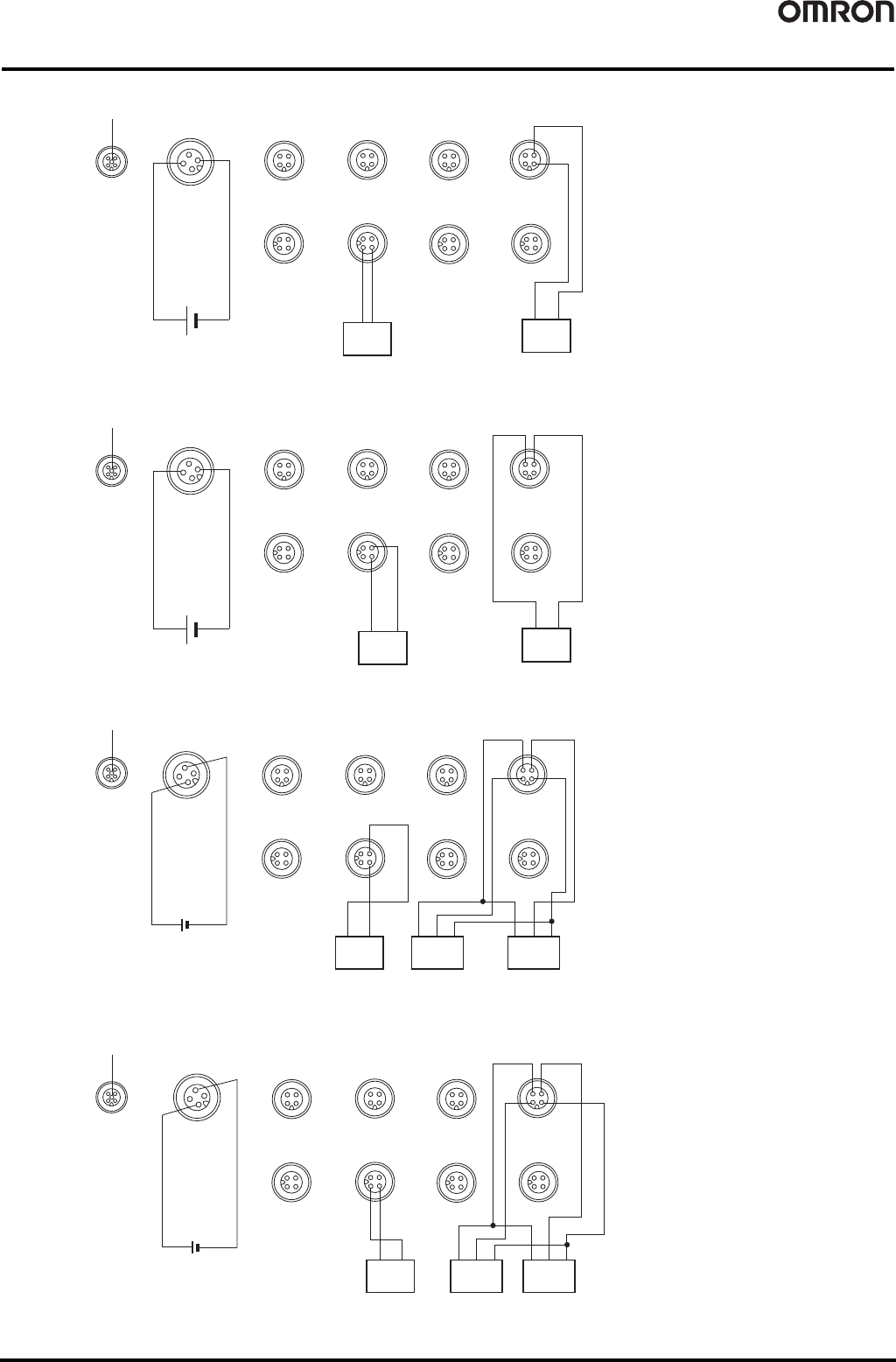
Environment-resistive Terminals with Transistors (Standard Type)
DRT2-
@
D04CL(-1)/
@
D08CL(-1)/
@
D16CL(-1)
55
DRT2-OD08CL (NPN)
DRT2-OD08CL-1 (PNP)
DRT2-HD16CL (NPN)
DRT2-HD16CL-1 (PNP)
1
2
4
3
V
Output 4
1
2
4
3
V
Output 2
1
2
4
3
V
Output 6
23
1
4
NC
VV
Output 1
V
2
3
1
4
Output 5
2
3
1
4
V
Output 3
23
1
4
V
Output 7
1
2
4
V+
CAN H
CAN L
?
3
5
V-
DRAIN
Solenoid valve, etc.
Solenoid valve, etc.
1
2
4
3
V
Output 0
2
NC
1
0V
3
24V
4
NC
I/O power supply
NC
NC
NC
NC
NC
NC
NC
NC
NC
NC NC
NC
NC
NC NC
1
2
4
3
Output 4
1
2
4
3
Output 2
1
2
4
3
Output 6
2 3
1
4
NC
Output 1
2
3
1
4
Output 5
2
3
1
4
Output 3
23
1
4
Output 7
1
2
4
V+
CAN H
CAN L
3
5
V-
DRAIN
Solenoid valve, etc.
Solenoid valve, etc.
1
2
4
3
Output 0
2
NC
1
0V
3
24V
4
NC
I/O power supply
NC
NC
NC
NC
NC
NC
NC
NC
NC
NC
NC
NC
NC
NC
NC
G
G
G
G
G
G
G
G
Three-wire sensor with
NPN output
(e.g., photoelectric sensor
or proximity sensor)
Three-wire sensor with
NPN output
(e.g., photoelectric sensor
or proximity sensor)
Two-wire sensor
(Limit switch, etc.)
I/O power supply 24 VDC
Brown
(white)
Blue
(black)
Blue
(black)
Brown
(red)
Black
(White)
Blue
(black)
Brown
(red)
Black
(White)
1
2
4
3
V
G
Input 0
1
2
4
3
V
G
Input 8
1
2
4
3
V
G
Input 4
1
2
4
3
V
G
Input 12
23
1
4
NC
V
G
Input 2
2 3
1
4
V
G
Input 10
23
1
4
V
G
Input 6
2 3
1
4
V
G
Input 14
1
2
4
V+
CAN H
CAN L
3
5
V-
DRAIN
Input 1
Input 3
Input 5
Input 9
Input 13
Input 15
Input 11
Input 7
1
2
4
3
NC
NC
24V
0V
Three-wire sensor
with PNP output
(e.g., photoelectric
sensor or proximity
sensor)
Three-wire sensor
with PNP output
(e.g., photoelectric
sensor or proximity
sensor)
Two-wire sensor
(Limit switch, etc.)
1
2
4
3
V
G
Input 0
1
2
4
3
V
G
Input 8
1
2
4
3
V
G
Input 4
1
2
4
3
V
G
Input
12
2 3
1
4
NC
V
G
Input 2
2 3
1
4
V
G
Input 10
2 3
1
4
V
G
Input 6
2 3
1
4
V
G
Input 14
1
2
4
V+
CAN H
CAN L
3
5
V-
DRAIN
Input 1
Input 3
Input 5
Input 9
Input 13
Input 15
Input 11
Input 7
1
2
4
3
NC
NC
24V
0V
I/O power supply 24 VDC
Brown
(white)
Blue
(black)
Blue
(black)
Brown
(red)
Black
(White)
Blue
(black)
Brown
(red)
Black
(White)
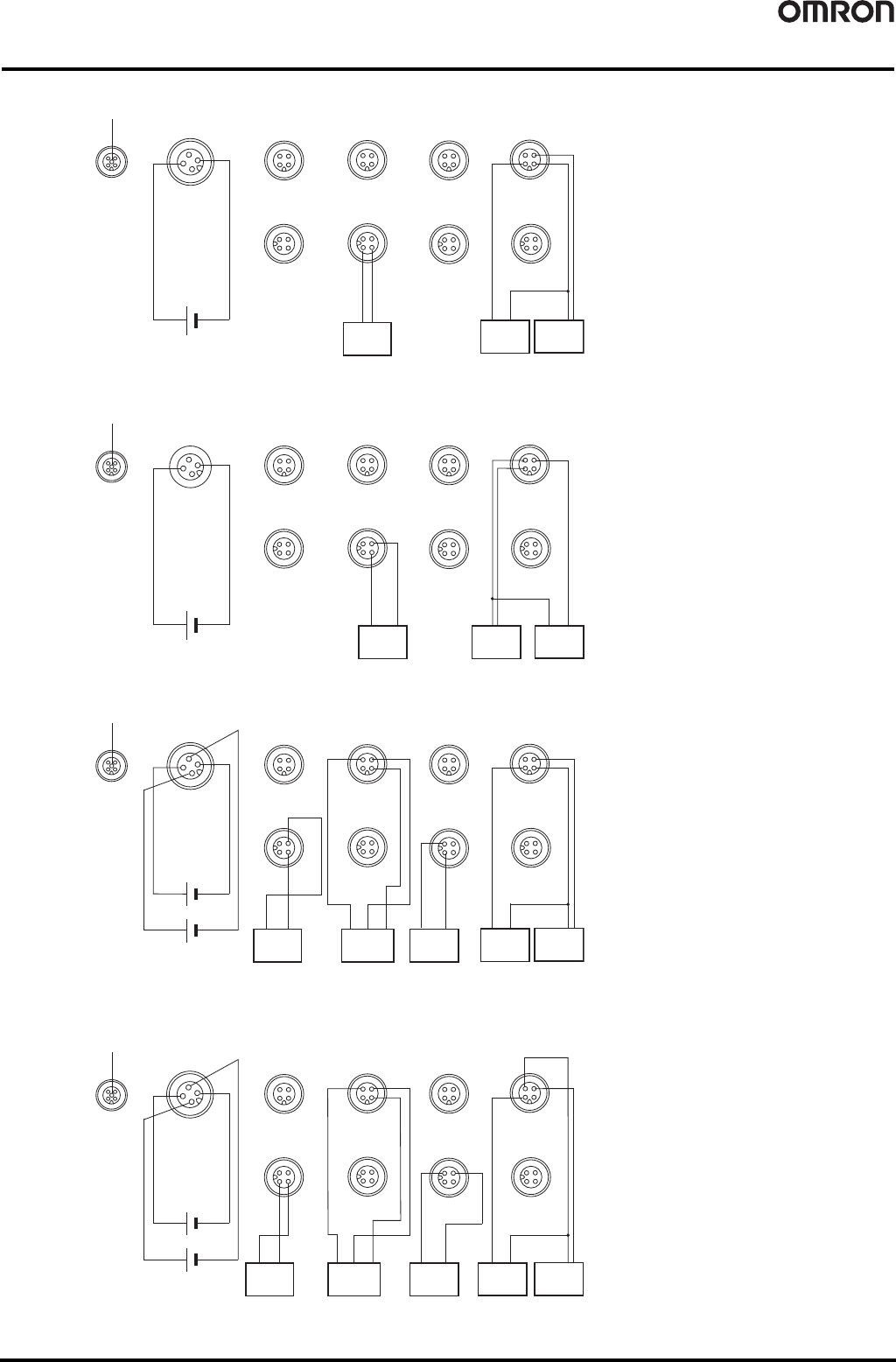
56
Environment-resistive Terminals with Transistors (Standard Type)
DRT2-
@
D04CL(-1)/
@
D08CL(-1)/
@
D16CL(-1)
DRT2-WD16CL (NPN)
DRT2-WD16CL-1 (PNP)
DRT2-MD16CL (NPN)
DRT2-MD16CL-1 (PNP)
1
2
4
3
V
Output 8
1
2
4
3
V
Output 4
1
2
4
3
V
Output 12
23
1
4
V
Output 2
2
3
1
4
Output 10
2
3
1
4
V
Output 6
2 3
1
4
V
Output 14
1
2
4
V+
CAN H
CAN L
3
5
V-
DRAIN
Solenoid valve, etc.
Solenoid valve, etc.
1
2
4
3
V
Output 0
2
NC
1
0V
3
24V
4
NC
NC
NC
NC
NC
NC
NC
NC
NC
Output 1
Output 3
Output 5
Output 7
Output 9
Output 11
Output 13
Output 15
V
I/O power supply
1
2
4
3
Output 8
1
2
4
3
Output 4
1
2
4
3
Output 12
23
1
4
Output 2
2
3
1
4
Output 10
2
3
1
4
Output 6
23
1
4
Output 14
1
2
4
V+
CAN H
CAN L
3
5
V-
DRAIN
1
2
4
3
Output 0
2
NC
1
0V
3
24V
4
NC
NC
NC
NC
NC
NC
NC
NC
NC
G
G
G
G
G
G
GG
Output 1
Output 3
Output 5
Output 7
Output 9
Output 11
Output 13
Output 15
Solenoid valve, etc. Solenoid valve, etc.
I/O power supply
Three-wire sensor with
NPN output
(e.g., photoelectric sensor
or proximity sensor)
Two-wire sensor
(Limit switch, etc.)
Brown
(white)
Blue
(black)
Blue
(black)
Brown
(red)
Black
(White)
1
2
4
3
V2
Output 0
1
2
4
3
Input 4
1
2
4
3
V2
OUT4
23
1
4
V1
Input 2
V2
2
3
1
4
Output 2
2
3
1
4
V1
Input 6
2 3
1
4
V2
Output 6
1
2
4
V+
CAN H
CAN L
3
5
V-
DRAIN
Solenoid valve, etc.
1
2
4
3
V1
Input 0
2
V2
1
G2
3
4
V1
G1
G1
G1
G1
NC
NC
NC
NC
Input 1
Input 3
Input 5
Input 7
Output 1
Output 3
Output 5
Output 7
24 V for output
24 V for input
V1
Solenoid
valve, etc.
G1
I/O power supply
Three-wire sensor with
NPN output
(e.g., photoelectric sensor
or proximity sensor)
Two-wire sensor
(Limit switch, etc.)
Brown
(white)
Blue
(black)
Blue
(black)
Brown
(red)
Black
(White)
1
2
4
3
NC
Output 0
1
2
4
3
Input 4
1
2
4
3
NC
OUT4
2 3
1
4
V1
Input 2
2
3
1
4
Output 2
2
3
1
4
V1
Input 6
2 3
1
4
NC
NC
Output 6
1
2
4
V+
CAN H
CAN L
3
5
V-
DRAIN
1
2
4
3
V1
Input 0
2
V2
1
G2
3
4
V1
I/O power supply
G1
G1
NC
G1
G2
G2
G2
G2
Input 1
Input 3
Input 5
Input 7
Output 1
Output 3
Output 5
Output 7
24 V for output
24 V for input
V1
G1
Solenoid valve, etc.Solenoid valve, etc.
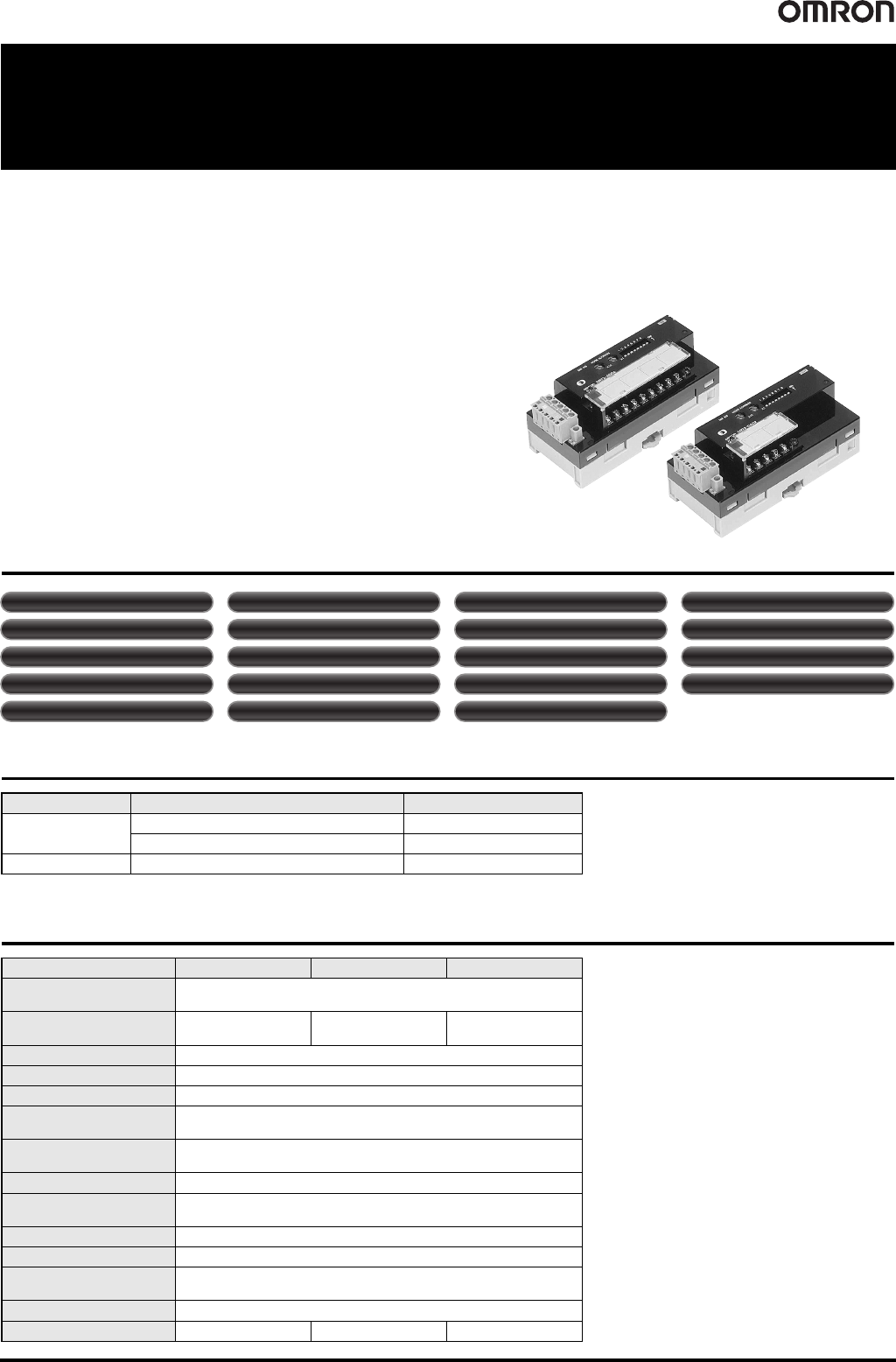
Analog I/O Terminals DRT2-AD04(H)/DA02 57
Analog I/O Terminals
DRT2-AD04(H)/DA02
Performs Calculations on Analog Values within the Slave Itself.
Also Provides High Resolution at 1/30,000 (Full Scale) and
Support for a Wide Variety of Data Sampling.
• Equipped with the standard Smart Slave functions that provide powerful
preventative maintenance and troubleshooting capabilities.
• Sampling data can be analyzed internally to provide a low-cost scheduler
function.
• Equipped with functions such as the scaling function, peak/bottom hold;
top/valley hold; comparator function, cumulative counter, and derivative
calculation function.
• Two I/O points can be allocated to any two of the following values: analog
input, peak/bottom, top, valley, or rate-of-change. Values without an
allocated I/O point can be read with message communications.
Smart Slave Functions
Ordering Information
*1. Product no longer available to order.
General Specifications
Classification I/O points Model
Analog input
4 inputs (Resolution: 6, 000) DRT2-AD04
*1
4 inputs (Resolution: 30, 000) DRT2-AD04H
Analog ou
tput 2 outputs DRT2-DA02 *1
Item Model DRT2-AD04 DRT2-AD04H DRT2-DA02
Communications power
supply voltage
11 to 25 VDC (Supplied from the communications connector)
Current consumption
90 mA max. (24 VDC)
150 mA max. (11V DC)
70 mA max. (24 VDC)
110 mA max. (11 VDC)
120 mA max. (24 VDC)
220 mA max. (11 VDC)
Noise immunity Conforms to IEC61000-4-4, 2 kV (power line)
Vibration resistance 10 to 150 Hz, 0.7-mm double amplitude
Shock resistance 150 m/s
2
Dielectric strength
500 VAC for 1 min between the communications circuit and analog circuit
(1 mA sensing current)
Ambient operating
temperature
-10°C to 55°C (with no icing or condensation)
Ambient operating humidity 25% to 85%
Ambient operating
atmosphere
No corrosive gases
Ambient storage temperature -20°C to 65°C
Mounting method DIN 35 mm-track mounting
Mounting strength
50 N
10 N (in the DIN Track direction)
Screw tightening torque M3 (power, I/O terminal): 0.5 N·m
Weight 170 g max. 160 g max. 150 g max.
Unit conduction time monitor Unit comments Connected device comments
Network power supply voltage monitor
Communications error log function Removable terminal block
Automatic baud rate detection. No wiring required.
No need to wire Unit power supply
Scaling User calibration Last maintenance date Integration
Moving averaging (inputs only)
AD conversion points (conversion cycle) setting (inputs only)
Peak/bottom hold To p/ valley hold Rate of change calculation
Comparator
Error output value setting (outputs only)