drt2_devicenet_q102-e1_20_22_csm2147.pdf - 第108页
88 Programmab le Slaves CPM2C-S1 @ 0C-DRT Programmable Slaves CPM2C-S1 @ 0C-DRT Slaves with the Complex Functionality Needed for Distributed Blocks Programmable Sla ves combine devices, su ch as sensors and actuator s, i…

87
Intelligent Slaves (PLC Units)
Programmable Slaves ..................................................................................... 88
CPM2C-S1@0C-DRT
88 Programmable Slaves CPM2C-S1@0C-DRT
Programmable Slaves
CPM2C-S1@0C-DRT
Slaves with the Complex Functionality Needed
for Distributed Blocks
Programmable Slaves combine devices, such as sensors and actuators, into one
functional unit that is treated as a DeviceNet slave.
Programmable Slaves greatly facilitate device distribution and functional organization.
They help standardize programming between units and reduce the amount of
programming required at the master.
I/O and operational checks can be performed for each functional unit, rather than waiting
for final system assembly, as with conventional distributed I/O systems.
• A Programmable Slave can be programmed from a CX-Programmer up to 3 network levels away.
(Includes the DeviceNet network itself. Possible only with CX-Programmer Ver. 2.1 or later and a
Programmable Slave Ver. 1.04 or later.)
• DeviceNet Slave Functions
Multiword I/O links and explicit messages are used to control slaves from the master. Log data for communications can be sent in one
operation whenever necessary using explicit messages.
• CompoBus/S Master Functions
Less wiring is required for terminal block expansions, connections to remote devices (such as signal lights or pushbutton switches), and
connections to pneumatic valves and other non-OMRON products. Connect using VCTF cable or Special Flat Cable, which allows easy
branching.
• RS-232C Communications
Connected to bar code readers, Programmable Terminals, and other devices, the Programmable Slave processes data locally to reduce
the load on the master.
• Expansion Units (3 max.)
Just one Unit is required for each distributed block, reducing the number of interfaces for multipoint communications to, in turn, reduce
costs.
Ordering Information
Note 1: For details on CPM2C PLCs, refer to the CPM2A/CPM2C Catalog (P049).
Note 2: For details on Programmable Slave specifications, refer to the Programmable Slave Catalog (R071).
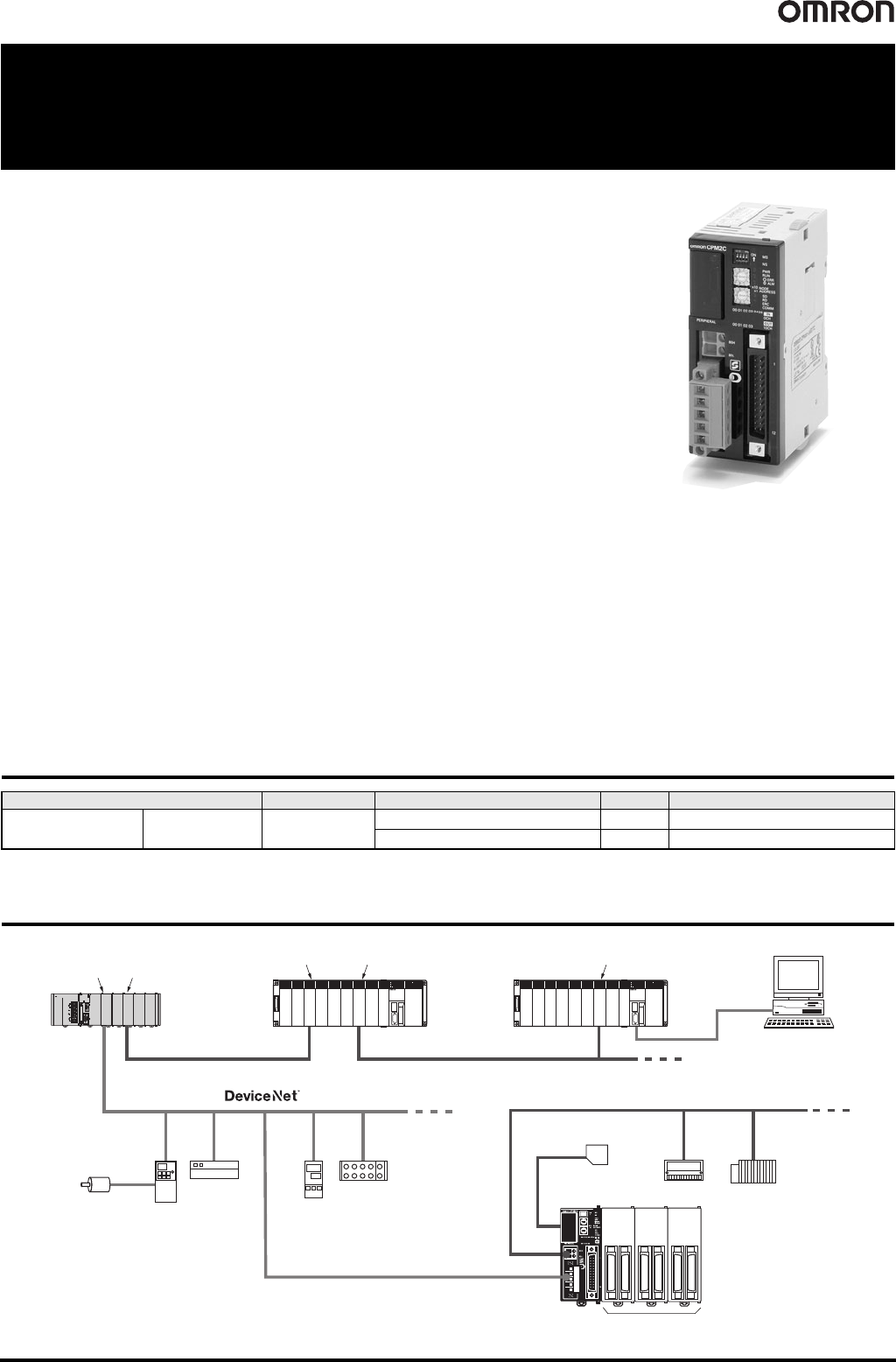
System Configuration
Unit type Input Output Clock Model
10 I/O points
6 inputs; 4 outputs
Connector 6 points: 24 VDC
4 points: transistor (sinking) Yes CPM2C-S100C-DRT
4 points: transistor (sourcing) Yes CPM2C-S110C-DRT
CompoBus/S
Controller Link Ethernet
Programmable Slave
CPM2C-S1@0C-DRT
RS-232C
CS/CJ-series
DeviceNet Unit
CS/CJ-series
Controller Link Unit
CS/CJ-series
Controller Link Unit
Ethernet Unit Ethernet Unit
CX-Programmer
Expansion Units (3 max.)
RUN
ERR
INH
COMM
POWER
PROGRAMMABLE CONTROLLER
CPU64
SYSMAC C200HX
RUN
ERR
INH
COMM
POWER
PROGRAMMABLE CONTROLLER
CPU64
SYSMAC C200HX
POWER
PA205R
DC24V
AC240V
OUTPUT
RUN
INPUT
AC100-240V
L2/N
L1
CONTROLLER
CJ1G-CPU44
SYSMAC
PROGRAMMABLE
ERR/ALM
RUN
COMM
INH
PRPHL
OPEN
PERIPHERAL
BUSY
MCPWR
PORT
Programmable Slaves CPM2C-S1@0C-DRT 89
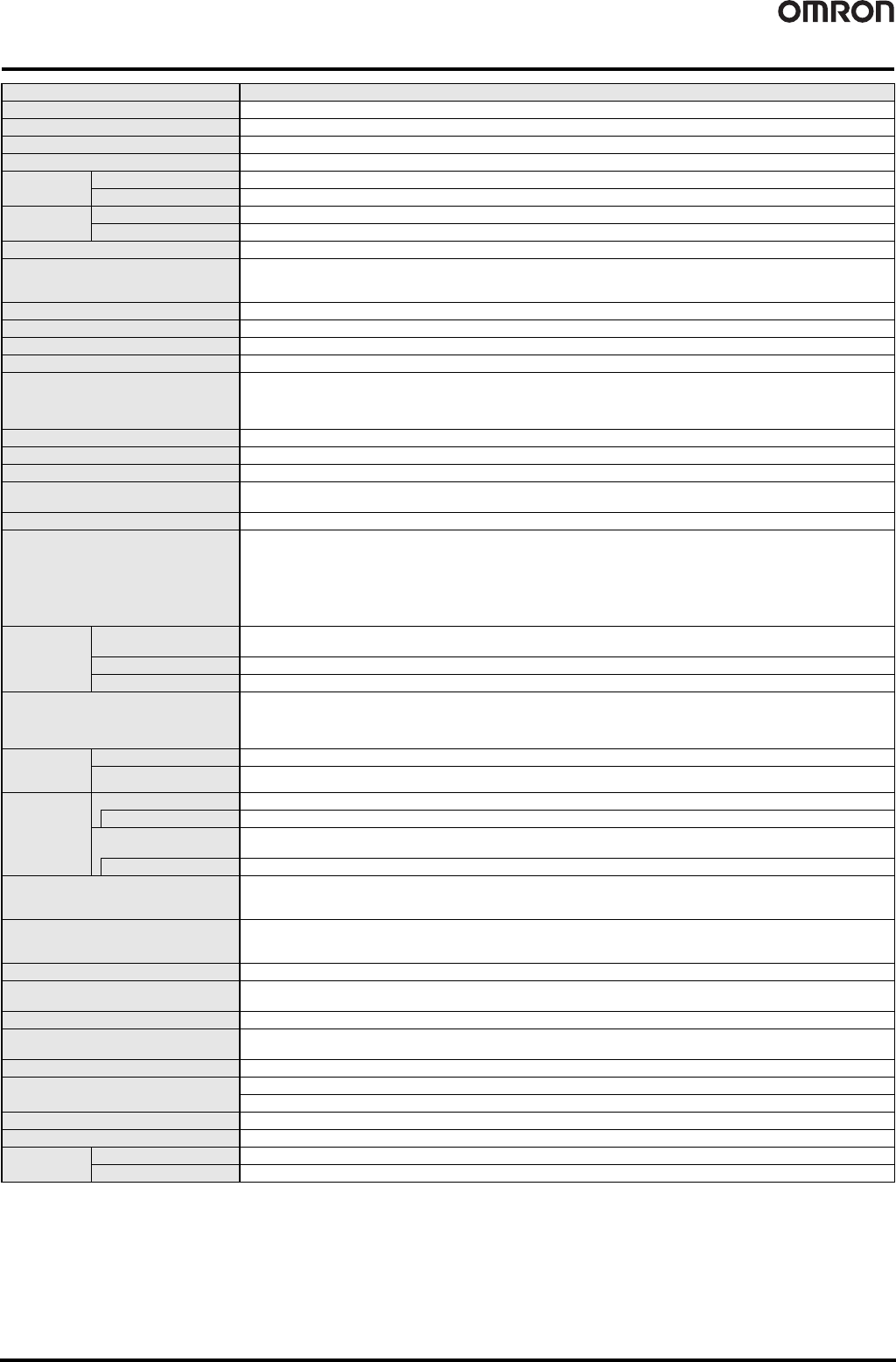
General Specifications and Performance Specifications
* A Connecting Cable (CPM2C-CN111, CS1W-CN114, or CS1W-CN118) is required to connect to the communications (peripheral/RS-232C) port.
Item Specifications
Control method Stored program method
I/O control method Cyclic scan method (Immediate refreshing can be performed with IORF instruction.)
Programming language Ladder diagram
Instruction length 1 step per instruction, 1 to 5 words per instruction
Instructions
Basic instructions 14 instructions
Special instructions 105 instructions, 185 variations
Execution
time
Basic instructions 0.64 s (LD instruction)
Special instructions 7.8 s (MOV instruction)
Program capacity 4,096 words
Maximum I/O points
CPU Unit only: 10 points
Expansion I/O: 96 points (32-point Expansion I/O Unit × 3)
CompoBus/S: 256 points (362 in total)
Input bits IR 00000 to IR 00915 (Bits not used for input bits can be used for work bits.)
Output bits IR 01000 to IR 01915 (Bits not used for output bits can be used for work bits.)
CompoBus/S input bits 128 bits: IR 02000 to IR 02715 (Words IR 020 to IR 027)
CompoBus/S output bits 128 bits: IR 03000 to IR 03715 (Words IR 030 to IR 037)
Work bits
672 bits: IR 02800 to IR 02915 (Words IR 028 to IR 029)
IR 03800 to IR 03915 (Words IR 038 to IR 039)
IR 04000 to IR 04915 (Words IR 040 to IR 049)
IR 20000 to IR 22715 (Words IR 200 to IR 227)
Special bits (SR area) 440 bits: SR 22800 to SR 25507 (Words IR 228 to IR 225)
Temporary bits (TR area) 8 bits (TR0 to TR7)
Holding bits (HR area) 320 bits: HR 0000 to HR 1915 (Words HR 00 to HR19)
Auxiliary bits (AR area)
384 bits: AR 0000 to AR 2315 (Words AR 00 to AR23)
These include the CompoBus/S slave status flags (AR 04 to 07).
Link bits (LR area) 256 points: LR 0000 to LR 1515 (Words LR 00 to LR 15)
Timers/Counters
256 timers/counters: TIM/CNT 000 to TIM/CNT 255
1-ms timers: TMHH
10-ms timers: TIMH
100-ms timers: TIM
1-s/10-s timers: TIML
Decrementing counters: CNT
Reversible counters: CNTR
Data memory
Read/Write
2,048 words (DM 0000 to DM 2047)
The Error Log is contained in DM 2000 to DM 2021.
Read-only 456 words (DM 6144 to DM 6599)
PC Setup 56 words (DM 6600 to DM 6655)
DeviceNet slave functions
DeviceNet Remote I/O Link
• Use up to 1,024 I/O points in the I/O Link.
Explicit Message Communications
• Any PC data area can be accessed from the master.
Basic
interrupt
functions
Interrupt inputs 2 interrupts (Used for both counter mode interrupt inputs and quick-response inputs.)
Scheduled interrupts 1 interrupt
High-speed
counter
functions
High-speed counters 1 counter (20 kHz single-phase or 5 kHz 2-phase)
Counter interrupts 1 interrupt (set value comparison or set-value range comparison)
Interrupt inputs (counter
mode)
2 interrupts (Used for both external interrupt inputs and quick-response inputs.)
Count-up interrupts 2 interrupts (Used for both external interrupt inputs and quick-response inputs.)
Quick-response inputs
2 inputs
(Used for both external interrupt inputs and counter mode interrupt inputs.)
Min. input pulse width: 50 s max.
Pulse output
2 points without acceleration/deceleration, 10 Hz to 10 kHz each, and no direction control;
1 point with trapezoid acceleration/deceleration, 10 Hz to 10 kHz, and direction control;
2 points with variable duty-ratio outputs
Synchronized pulse control 1 point
Input time constant
(ON response time = OFF response time)
Can be set for CPU inputs and Expansion Unit inputs only.
(1 ms, 2 ms, 3 ms, 5 ms, 10 ms, 20 ms, 40 ms, or 80 ms)
Clock Equipped with clock (built-in RTC)
Communications functions
Peripheral port: Supports Host Link, peripheral bus, no-protocol, or Programming Console connections.
RS-232C port: Supports Host Link, no-protocol, 1:1 Link, or 1:1 NT Link connections.
Memory protection HR area, AR area, program contents, DM area contents, and counter values maintained during power interruptions.
Memory backup
Non-volatile (flash) memory: Program, read-only DM area, and PC Setup
Memory backup (lithium battery; 2-year lifetime): DM area, HR area, AR area, and counter values
Self-diagnostic functions CPU errors (watchdog timer), memory errors, communications errors, setting errors, battery errors, and expansion I/O bus errors
Program checks No END instruction, programming errors (checked when operation is started)
Programming
Devices
Programming Console C200H-PRO27
CX-Programmer Windows edition