drt2_devicenet_q102-e1_20_22_csm2147.pdf - 第41页
Transistor R emote I/O Te rminals DRT2- @ D08(-1)/ @ D16(-1) 21 DRT2-ID16 (NPN) DRT2-ID16-1 (PNP) DRT2-OD16 (NPN) DRT2-OD16-1 (PNP) DRT2-MD16 (NPN) DRT2-MD16-1 (PNP) 9 8 11 10 13 12 15 14 V 10 1 11 3 12 5 13 7 14 15 G 02…
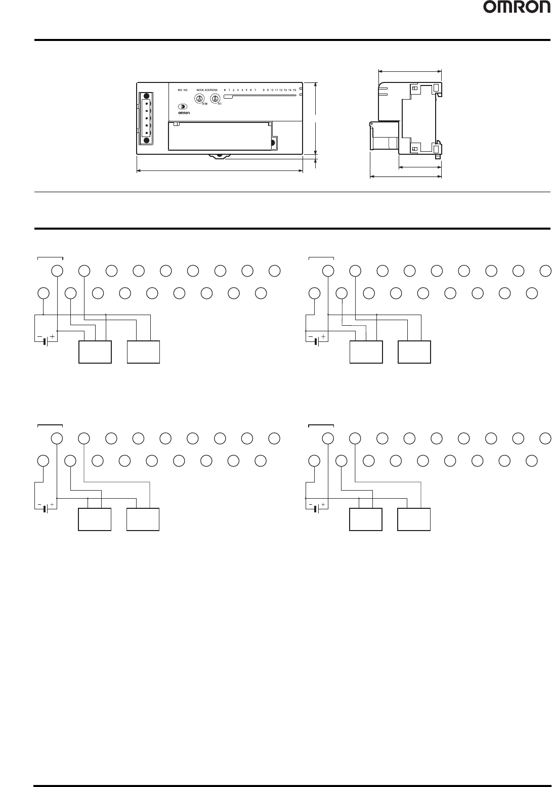
20 Transistor Remote I/O Terminals DRT2-@D08(-1)/@D16(-1)
Dimensions (Unit: mm)
Wiring Diagrams
DRT2-ID08 (NPN) DRT2-ID08-1 (PNP)
DRT2-OD08 (NPN) DRT2-OD08-1 (PNP)
49.6
29.8
43.8
50
3.1
115
DRT2-ID16(-1)
DRT2-OD16(-1)
DRT2-ID08(-1)
DRT2-OD08(-1)
DRT2-MD16(-1)
NC
NC
NC
NC
NC
NC
NC
NC
V
10
1
11
3
12
5
13
7
14 15
G
02
3
4
4
6
56
24 VDC
16 17 18
789
12
Two-wire sensor
(Limit switch, etc.)
Three-wire sensor
with NPN output
(e.g., photoelectric
sensor or proximity sensor)
I/O power
supply
Brown
(red)
Black
(white)
Blue
(black)
Brown
(white)
Blue
(black)
NC
NC
NC
NC
NC
NC
NC
NC
V
10
1
11
3
12
5
13
7
14 15
G
02
3
4
4
6
56
24 VDC
16 17 18
789
12
Two-wire sensor
(Limit switch, etc.)
Three-wire sensor
with PNP output
(e.g., photoelectric
sensor or proximity sensor)
I/O power
supply
Brown
(red)
Black
(white)
Blue
(black)
Brown
(white)
Blue
(black)
I/O power
supply
NC
NC
NC
NC
NC
NC
NC
NC
V
10
1
11
3
12
5
13
7
14 15
G
02
3
4
4
6
56
24 VDC
16 17 18
789
12
Solenoid
valve, etc.
Solenoid
valve, etc.
NC
NC
NC
NC
NC
NC
NC
NC
V
10
1
11
3
12
5
13
7
14 15
G
02
3
4
4
6
56
24 VDC
16 17 18
789
12
I/O power
supply
Solenoid
valve, etc.
Solenoid
valve, etc.
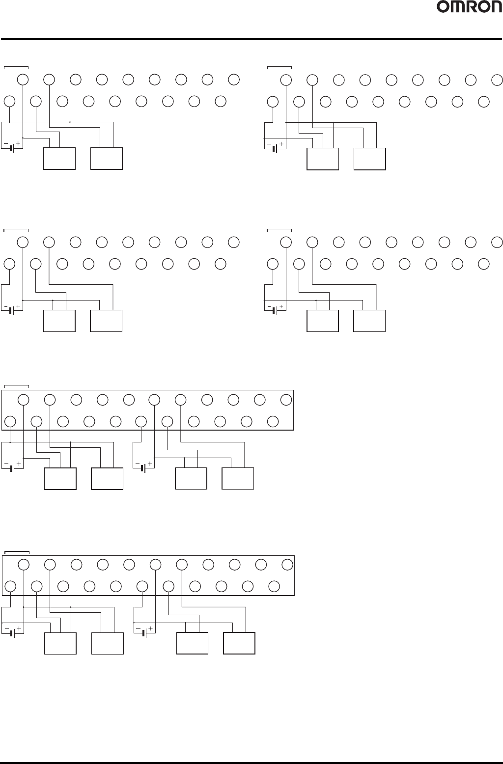
Transistor Remote I/O Terminals DRT2-@D08(-1)/@D16(-1) 21
DRT2-ID16 (NPN) DRT2-ID16-1 (PNP)
DRT2-OD16 (NPN) DRT2-OD16-1 (PNP)
DRT2-MD16 (NPN)
DRT2-MD16-1 (PNP)
9
8
11
10
13
12
15
14
V
10
1
11
3
12
5
13
7
14 15
G
02
3
4
4
6
56
24 VDC
16 17 18
789
12
Two-wire sensor
(Limit switch, etc.)
Three-wire sensor
with NPN output
(e.g., photoelectric
sensor or proximity sensor)
I/O power
supply
Brown
(red)
Black
(white)
Blue
(black)
Brown
(white)
Blue
(black)
9
8
11
10
13
12
15
14
V
10
1
11
3
12
5
13
7
14 15
G
02
3
4
4
6
56
24 VDC
16 17 18
789
12
Two-wire sensor
(Limit switch, etc.)
Three-wire sensor
with PNP output
(e.g., photoelectric
sensor or proximity sensor)
I/O power
supply
Brown
(red)
Black
(white)
Blue
(black)
Brown
(white)
Blue
(black)
9
8
11
10
13
12
15
14
V
10
1
11
3
12
5
13
7
14 15
G
02
3
4
4
6
56
24 VDC
16 17 18
789
12
I/O power
supply
Solenoid
valve, etc.
Solenoid
valve, etc.
9
8
11
10
13
12
15
14
V
10
1
11
3
12
5
13
7
14 15
G
02
3
4
4
6
56
24 VDC
16 17 18
789
12
I/O power
supply
Solenoid
valve, etc.
Solenoid
valve, etc.
V11357
G1
0246
24 VDC
V21357
G2
0246
NC
NC
I/O power
supply
Solenoid
valve, etc.
Solenoid
valve, etc.
Two-wire sensor
(Limit switch, etc.)
Three-wire sensor
with NPN output
(e.g., photoelectric
sensor or proximity sensor)
I/O power
supply
Brown
(red)
Black
(white)
Blue
(black)
Brown
(white)
Blue
(black)
V1 1 3 5 7
G1
0246
24 VDC
NC
NC
V21357
G2
0246
I/O power
supply
Solenoid
valve, etc.
Solenoid
valve, etc.
Two-wire sensor
(Limit switch, etc.)
Three-wire sensor
with NPN output
(e.g., photoelectric
sensor or proximity sensor)
I/O power
supply
Brown
(red)
Black
(white)
Blue
(black)
Brown
(white)
Blue
(black)
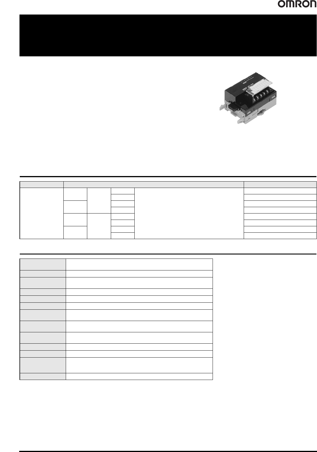
22 Expansion Units XWT-ID08(-1)/OD08(-1)/ID16(-1)/OD16(-1)
Expansion Units
XWT-ID08(-1)/OD08(-1)/ID16(-1)/OD16(-1)
Expansion I/O Units make expansion
easy!
One Expansion Unit can be added to each Digital I/O Slave Unit.
This makes a variety of I/O combinations possible, such as 16
inputs + 8 outputs, extending the range of possible system
configurations.
• Flexible expansion with many different combinations.
• Detachable I/O terminal block enables faster startup time and improved
maintainability.
• Collect various preventive maintenance data required to improve productivity, as
information on equipment deterioration due to aging and equipment operating time data.
Ordering Information
General Specifications
Name Specifications Model
Expansion Units
Inputs
8 points
NPN
One Expansion Unit can be mounted per
DRT2-ID16(-1)/-OD16(-1) or DRT2-ROS16
Remote I/O Terminal.
XWT-ID08
PNP
XWT-ID08-1
Outputs
NPN
XWT-OD08
PNP
XWT-OD08-1
Inputs
16 points
NPN
XWT-ID16
PNP
XWT-ID16-1
Outputs
NPN
XWT-OD16
PNP
XWT-OD16-1
I/O power supply
voltage
20.4 to 26.4 VDC (24 VDC -15%/+10%)
Noise immunity Conforms to IEC 61000-4-4 2 kV (power line).
Vibration resistance
10 to 60 Hz with double-amplitude of 0.7 mm, 60 to 150 Hz and 50 m/s
2
in X, Y, and Z
directions for 80 min each
Shock resistance 150 m/s
2
(3 times each in 6 directions on 3 axes)
Dielectric strength 500 VAC (between isolated circuits)
Insulation resistance 20 M min. (between isolated circuits)
Ambient operating
temperature
-10°C to 55°C
Ambient operating
humidity
25% to 85% (with no condensation)
Ambient operating
atmosphere
No corrosive gases
Storage temperature -25°C to 65°C
Storage humidity 25% to 85% (with no condensation)
Tightening torque for
the terminal block
screws
M3 terminal screws: 0.5 N
·m
M3 mounting screws: 0.5 N
·m
Mounting method Mounted on 35-mm DIN Track